

487
13.3 Radial Flow Variation
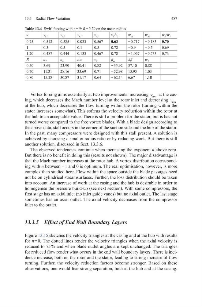
Vortex forcing aims essentially at two improvements: increasing v um at the casing, which decreases the Mach number level at the rotor inlet and decreasing v um
at the hub, which decreases the flow turning within the rotor (turning within the
stator increases somewhat). This softens the velocity reduction within the rotor at
the hub to an acceptable value. There is still a problem for the stator, but is has not
turned worse compared to the free vortex blades. With a blade design according to
the above data, stall occurs in the corner of the suction side and the hub of the stator.
In the past, many compressors were designed with this stall present. A solution is
achieved by choosing a smaller radius ratio or by reducing work. But there is still
another solution, discussed in Sect. 13.3.6.
The observed tendencies continue when increasing the exponent n above zero.
But there is no benefit in doing this (results not shown). The major disadvantage is
that the Mach number increases at the rotor hub. A vortex distribution corresponding with n between − 1 and 0 is optimum. The real optimisation, however, is more
complex than studied here. Flow within the space outside the blade passages need
not be on cylindrical streamsurfaces. Further, the loss distribution should be taken
into account. An increase of work at the casing and the hub is desirable in order to
homogenise the pressure build-up (see next section). With some compressors, the
first stage has an axial inlet (no inlet guide vanes) but no axial outlet. The last stage
sometimes has an axial outlet. The axial velocity decreases from the compressor
inlet to the outlet.
13.3.5 Effect of End Wall Boundary Layers
Figure 13.15 sketches the velocity triangles at the casing and at the hub with results
for n = 0. The dotted lines render the velocity triangles when the axial velocity is
reduced to 75 % and when blade outlet angles are kept unchanged. The triangles
for reduced flow render what occurs in the end wall boundary layers. There is incidence increase, both on the rotor and the stator, leading to strong increase of flow
turning. Further, the velocity reduction factors become stronger. Based on these
observations, one would fear strong separation, both at the hub and at the casing.
Table 13.4 Swirl forcing with n = 0; R = 0.70 on the mean radius
u
v a1
v a2
v u1
v u2
v 1 /v 2
w u1
w u2
w 2 /w 1
0.75
0.512
0.585
0.033
0.567
0.63
− 0.717 − 0.183 0.70
1
0.5
0.5
0.1
0.5
0.72
− 0.9
− 0.5
0.69
1.20
0.487
0.444
0.133
0.467
0.78
− 1.067 − 0.733 0.73
R
α 1
α m
Δα
v 2
β m
Δβ
w 1
0.50
3.69
23.90
40.41
0.82
− 35.92 37.10
0.88
0.70
11.31
28.16
33.69
0.71
− 52.98 15.95
1.03
0.80
15.28
30.87
31.17
0.64
− 62.14 6.67
1.18
13.3 Radial Flow Variation
Vortex forcing aims essentially at two improvements: increasing v um at the casing, which decreases the Mach number level at the rotor inlet and decreasing v um
at the hub, which decreases the flow turning within the rotor (turning within the
stator increases somewhat). This softens the velocity reduction within the rotor at
the hub to an acceptable value. There is still a problem for the stator, but is has not
turned worse compared to the free vortex blades. With a blade design according to
the above data, stall occurs in the corner of the suction side and the hub of the stator.
In the past, many compressors were designed with this stall present. A solution is
achieved by choosing a smaller radius ratio or by reducing work. But there is still
another solution, discussed in Sect. 13.3.6.
The observed tendencies continue when increasing the exponent n above zero.
But there is no benefit in doing this (results not shown). The major disadvantage is
that the Mach number increases at the rotor hub. A vortex distribution corresponding with n between − 1 and 0 is optimum. The real optimisation, however, is more
complex than studied here. Flow within the space outside the blade passages need
not be on cylindrical streamsurfaces. Further, the loss distribution should be taken
into account. An increase of work at the casing and the hub is desirable in order to
homogenise the pressure build-up (see next section). With some compressors, the
first stage has an axial inlet (no inlet guide vanes) but no axial outlet. The last stage
sometimes has an axial outlet. The axial velocity decreases from the compressor
inlet to the outlet.
13.3.5 Effect of End Wall Boundary Layers
Figure 13.15 sketches the velocity triangles at the casing and at the hub with results
for n = 0. The dotted lines render the velocity triangles when the axial velocity is
reduced to 75 % and when blade outlet angles are kept unchanged. The triangles
for reduced flow render what occurs in the end wall boundary layers. There is incidence increase, both on the rotor and the stator, leading to strong increase of flow
turning. Further, the velocity reduction factors become stronger. Based on these
observations, one would fear strong separation, both at the hub and at the casing.
Table 13.4 Swirl forcing with n = 0; R = 0.70 on the mean radius
u
v a1
v a2
v u1
v u2
v 1 /v 2
w u1
w u2
w 2 /w 1
0.75
0.512
0.585
0.033
0.567
0.63
− 0.717 − 0.183 0.70
1
0.5
0.5
0.1
0.5
0.72
− 0.9
− 0.5
0.69
1.20
0.487
0.444
0.133
0.467
0.78
− 1.067 − 0.733 0.73
R
α 1
α m
Δα
v 2
β m
Δβ
w 1
0.50
3.69
23.90
40.41
0.82
− 35.92 37.10
0.88
0.70
11.31
28.16
33.69
0.71
− 52.98 15.95
1.03
0.80
15.28
30.87
31.17
0.64
− 62.14 6.67
1.18