

478
13 Axial Compressors
13.1.12 Attainable Pressure Ratio
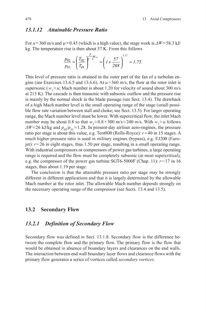
For u = 360 m/s and ψ = 0.45 (which is a high value), the stage work is ΔW = 58.3 kJ/
kg. The temperature rise is then about 57 K. From this follows
This level of pressure ratio is attained in the outer part of the fan of a turbofan engine (see Exercises 13.6.5 and 13.6.6). At u = 360 m/s, the flow at the rotor inlet is
supersonic ( w 1 ≈ u; Mach number is about 1.20 for velocity of sound about 300 m/s
at 215 K). The cascade is then transonic with subsonic outflow and the pressure rise
is mainly by the normal shock in the blade passage (see Sect. 13.4). The drawback
of a high Mach number level is the small operating range of the stage (small possible flow rate variation between stall and choke; see Sect. 13.5). For larger operating
range, the Mach number level must be lower. With supercritical flow, the inlet Mach
number may be about 0.8 so that w 1 ≈ 0.8 × 300 m/s ≈ 240 m/s. With w 1 ≈ u follows
ΔW ≈ 26 kJ/kg and p 02 /p 01 ≈ 1.28. In present-day airliner aero-engines, the pressure
ratio per stage is about this value, e.g. Tent800 (Rolls-Royce): r = 40 in 15 stages. A
much higher pressure ratio is used in military engines (bypass), e.g. EJ200 (Eurojet): r = 26 in eight stages, thus 1.50 per stage, resulting in a small operating range.
With industrial compressors or compressors of power gas turbines, a large operating
range is required and the flow must be completely subsonic (at most supercritical),
e.g. the compressor of the power gas turbine SGT6-5000F (Chap. 11): r = 17 in 16
stages, thus about 1.19 per stage.
The conclusion is that the attainable pressure ratio per stage may be strongly
different in different applications and that it is largely determined by the allowable
Mach number at the rotor inlet. The allowable Mach number depends strongly on
the necessary operating range of the compressor (see Sects. 13.4 and 13.5).
13.2 Secondary Flow
13.2.1 Definition of Secondary Flow
Secondary flow was defined in Sect. 13.1.8. Secondary flow is the difference between the complete flow and the primary flow. The primary flow is the flow that
would be obtained in absence of boundary layers and clearances on the end walls.
The interaction between end wall boundary layer flows and clearance flows with the
primary flow generates a series of vortices called secondary vortices.
2
2
1
1
g h
g
∞
−
=
≈ +
≈
3.15
1
0
0
0
0
p
T
57
1
1.75.
p
T
288
13 Axial Compressors
13.1.12 Attainable Pressure Ratio
For u = 360 m/s and ψ = 0.45 (which is a high value), the stage work is ΔW = 58.3 kJ/
kg. The temperature rise is then about 57 K. From this follows
This level of pressure ratio is attained in the outer part of the fan of a turbofan engine (see Exercises 13.6.5 and 13.6.6). At u = 360 m/s, the flow at the rotor inlet is
supersonic ( w 1 ≈ u; Mach number is about 1.20 for velocity of sound about 300 m/s
at 215 K). The cascade is then transonic with subsonic outflow and the pressure rise
is mainly by the normal shock in the blade passage (see Sect. 13.4). The drawback
of a high Mach number level is the small operating range of the stage (small possible flow rate variation between stall and choke; see Sect. 13.5). For larger operating
range, the Mach number level must be lower. With supercritical flow, the inlet Mach
number may be about 0.8 so that w 1 ≈ 0.8 × 300 m/s ≈ 240 m/s. With w 1 ≈ u follows
ΔW ≈ 26 kJ/kg and p 02 /p 01 ≈ 1.28. In present-day airliner aero-engines, the pressure
ratio per stage is about this value, e.g. Tent800 (Rolls-Royce): r = 40 in 15 stages. A
much higher pressure ratio is used in military engines (bypass), e.g. EJ200 (Eurojet): r = 26 in eight stages, thus 1.50 per stage, resulting in a small operating range.
With industrial compressors or compressors of power gas turbines, a large operating
range is required and the flow must be completely subsonic (at most supercritical),
e.g. the compressor of the power gas turbine SGT6-5000F (Chap. 11): r = 17 in 16
stages, thus about 1.19 per stage.
The conclusion is that the attainable pressure ratio per stage may be strongly
different in different applications and that it is largely determined by the allowable
Mach number at the rotor inlet. The allowable Mach number depends strongly on
the necessary operating range of the compressor (see Sects. 13.4 and 13.5).
13.2 Secondary Flow
13.2.1 Definition of Secondary Flow
Secondary flow was defined in Sect. 13.1.8. Secondary flow is the difference between the complete flow and the primary flow. The primary flow is the flow that
would be obtained in absence of boundary layers and clearances on the end walls.
The interaction between end wall boundary layer flows and clearance flows with the
primary flow generates a series of vortices called secondary vortices.
2
2
1
1
g h
g
∞
−
=
≈ +
≈
3.15
1
0
0
0
0
p
T
57
1
1.75.
p
T
288