

476
13 Axial Compressors
aiming at a degree of reaction 50 % at the hub has no meaning. Further, the variation
of the degree of reaction from hub to casing is extreme, which means that the degree
of reaction at the hub must be small. The Mach number limitation at the rotor entrance at the tip of the rotor blade is crucial. This means that the velocity triangles at
the tip are still close to the triangles shown on top of Fig. 13.9, but with a somewhat
larger degree of reaction such that the entrance velocity v 1 is in the axial direction
(also a somewhat larger Mach number of the relative flow at rotor inlet). The hub
has a low degree of reaction. So, rotor flow turning becomes big near the hub and in
order to limit it, the work must be lowered near the hub (see Exercise 13.6.5). Thus,
the work cannot be constant along the radius.
13.1.11 Blade Shape
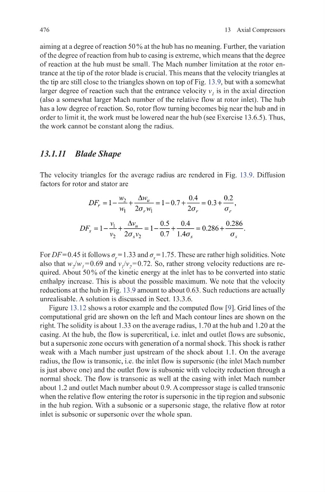
The velocity triangles for the average radius are rendered in Fig. 13.9. Diffusion
factors for rotor and stator are
For DF = 0.45 it follows σ r = 1.33 and σ s = 1.75. These are rather high solidities. Note
also that w 2 /w 1 = 0.69 and v 1 /v 2 = 0.72. So, rather strong velocity reductions are required. About 50 % of the kinetic energy at the inlet has to be converted into static
enthalpy increase. This is about the possible maximum. We note that the velocity
reductions at the hub in Fig. 13.9 amount to about 0.63. Such reductions are actually
unrealisable. A solution is discussed in Sect. 13.3.6.
Figure 13.12 shows a rotor example and the computed flow [9]. Grid lines of the
computational grid are shown on the left and Mach contour lines are shown on the
right. The solidity is about 1.33 on the average radius, 1.70 at the hub and 1.20 at the
casing. At the hub, the flow is supercritical, i.e. inlet and outlet flows are subsonic,
but a supersonic zone occurs with generation of a normal shock. This shock is rather
weak with a Mach number just upstream of the shock about 1.1. On the average
radius, the flow is transonic, i.e. the inlet flow is supersonic (the inlet Mach number
is just above one) and the outlet flow is subsonic with velocity reduction through a
normal shock. The flow is transonic as well at the casing with inlet Mach number
about 1.2 and outlet Mach number about 0.9. A compressor stage is called transonic
when the relative flow entering the rotor is supersonic in the tip region and subsonic
in the hub region. With a subsonic or a supersonic stage, the relative flow at rotor
inlet is subsonic or supersonic over the whole span.
2
1
1
0.4
0.2
1
1 0.7
0.3
,
2
2
u
r
r
r
r
w
w
DF
w
w
∆
= −
+
= −
+
=
+
s
s
s
1
2
2
0.5
0.4
0.286
1
1
0.286
.
2
0.7 1.4
u
s
s
s
s
v
v
DF
v
v
∆
= − +
= −
+
=
+
s
s
s
13 Axial Compressors
aiming at a degree of reaction 50 % at the hub has no meaning. Further, the variation
of the degree of reaction from hub to casing is extreme, which means that the degree
of reaction at the hub must be small. The Mach number limitation at the rotor entrance at the tip of the rotor blade is crucial. This means that the velocity triangles at
the tip are still close to the triangles shown on top of Fig. 13.9, but with a somewhat
larger degree of reaction such that the entrance velocity v 1 is in the axial direction
(also a somewhat larger Mach number of the relative flow at rotor inlet). The hub
has a low degree of reaction. So, rotor flow turning becomes big near the hub and in
order to limit it, the work must be lowered near the hub (see Exercise 13.6.5). Thus,
the work cannot be constant along the radius.
13.1.11 Blade Shape
The velocity triangles for the average radius are rendered in Fig. 13.9. Diffusion
factors for rotor and stator are
For DF = 0.45 it follows σ r = 1.33 and σ s = 1.75. These are rather high solidities. Note
also that w 2 /w 1 = 0.69 and v 1 /v 2 = 0.72. So, rather strong velocity reductions are required. About 50 % of the kinetic energy at the inlet has to be converted into static
enthalpy increase. This is about the possible maximum. We note that the velocity
reductions at the hub in Fig. 13.9 amount to about 0.63. Such reductions are actually
unrealisable. A solution is discussed in Sect. 13.3.6.
Figure 13.12 shows a rotor example and the computed flow [9]. Grid lines of the
computational grid are shown on the left and Mach contour lines are shown on the
right. The solidity is about 1.33 on the average radius, 1.70 at the hub and 1.20 at the
casing. At the hub, the flow is supercritical, i.e. inlet and outlet flows are subsonic,
but a supersonic zone occurs with generation of a normal shock. This shock is rather
weak with a Mach number just upstream of the shock about 1.1. On the average
radius, the flow is transonic, i.e. the inlet flow is supersonic (the inlet Mach number
is just above one) and the outlet flow is subsonic with velocity reduction through a
normal shock. The flow is transonic as well at the casing with inlet Mach number
about 1.2 and outlet Mach number about 0.9. A compressor stage is called transonic
when the relative flow entering the rotor is supersonic in the tip region and subsonic
in the hub region. With a subsonic or a supersonic stage, the relative flow at rotor
inlet is subsonic or supersonic over the whole span.
2
1
1
0.4
0.2
1
1 0.7
0.3
,
2
2
u
r
r
r
r
w
w
DF
w
w
∆
= −
+
= −
+
=
+
s
s
s
1
2
2
0.5
0.4
0.286
1
1
0.286
.
2
0.7 1.4
u
s
s
s
s
v
v
DF
v
v
∆
= − +
= −
+
=
+
s
s
s