

453
12.6 Technological Aspects of the Turbofan Engine
ber range in a compressor of an aero-engine is 0.55–0.65 in front stages, but
towards the exit this level is reduced to about 0.3 (velocity about 150 m/s). This
velocity level is still much too high for a stable combustion. The air is slowed
down by diffuser blades and by dump diffusion. A part of the air is supplied
centrally into the combustion chamber through the injectors (primary air). This
flow is split into two parts. Flow through the centre of the injector is forced into
swirl. The outside flow is forced into swirl as well, but in the opposite sense.
Fuel is injected as a liquid sheet between both contra-rotating air flows. The
high shear on the liquid flow atomises it into small drops. This disintegrating
mechanism enables variation of the fuel-air ratio over a large range, maintaining
stable combustion. The swirl of the inner air flow causes a low pressure zone
such that hot combustion products are sucked from downstream and transferred
to the injector by the recirculation flow pattern. This means that swirl stabilisation is used (see Chap. 11). Part of the air is added around the injector and serves
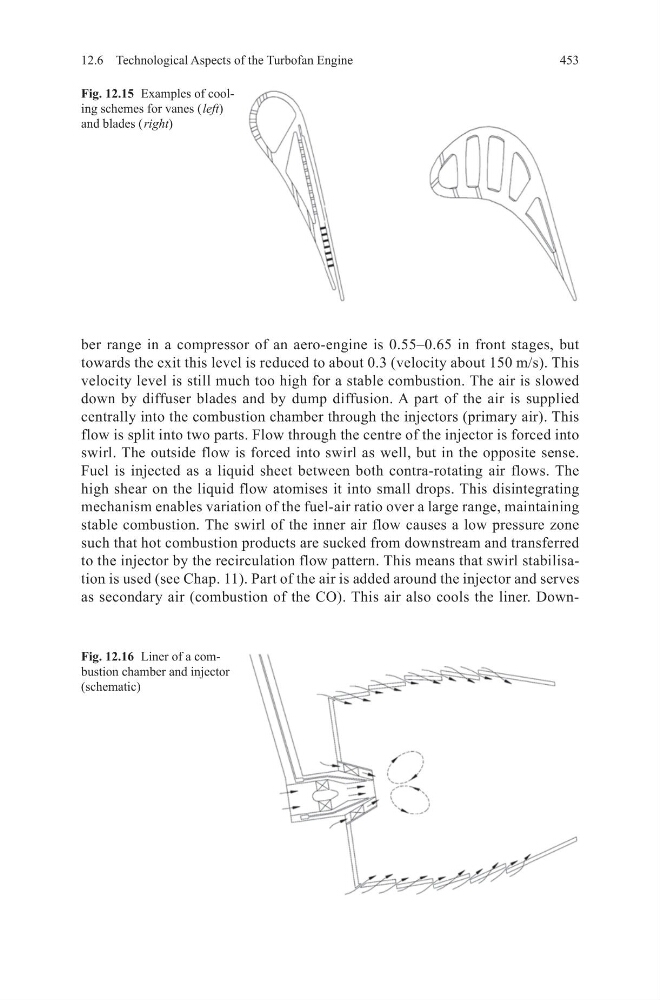
as secondary air (combustion of the CO). This air also cools the liner. DownFig. 12.15 Examples of cooling schemes for vanes ( left)
and blades ( right)
Fig. 12.16 Liner of a combustion chamber and injector
(schematic)
12.6 Technological Aspects of the Turbofan Engine
ber range in a compressor of an aero-engine is 0.55–0.65 in front stages, but
towards the exit this level is reduced to about 0.3 (velocity about 150 m/s). This
velocity level is still much too high for a stable combustion. The air is slowed
down by diffuser blades and by dump diffusion. A part of the air is supplied
centrally into the combustion chamber through the injectors (primary air). This
flow is split into two parts. Flow through the centre of the injector is forced into
swirl. The outside flow is forced into swirl as well, but in the opposite sense.
Fuel is injected as a liquid sheet between both contra-rotating air flows. The
high shear on the liquid flow atomises it into small drops. This disintegrating
mechanism enables variation of the fuel-air ratio over a large range, maintaining
stable combustion. The swirl of the inner air flow causes a low pressure zone
such that hot combustion products are sucked from downstream and transferred
to the injector by the recirculation flow pattern. This means that swirl stabilisation is used (see Chap. 11). Part of the air is added around the injector and serves
as secondary air (combustion of the CO). This air also cools the liner. DownFig. 12.15 Examples of cooling schemes for vanes ( left)
and blades ( right)
Fig. 12.16 Liner of a combustion chamber and injector
(schematic)