

447
12.5 Performance of Double-Flow Engines
Maximum thrust is attained for
(12.16)
Then
2
2
2
2
1
2
hot
b hot
b
b
s
s b s
h
h
= −
+
or
2
1
2
2
.
1
b
hot
b
b
s
s
b
h
h
+
= +
The resulting overall efficiency is
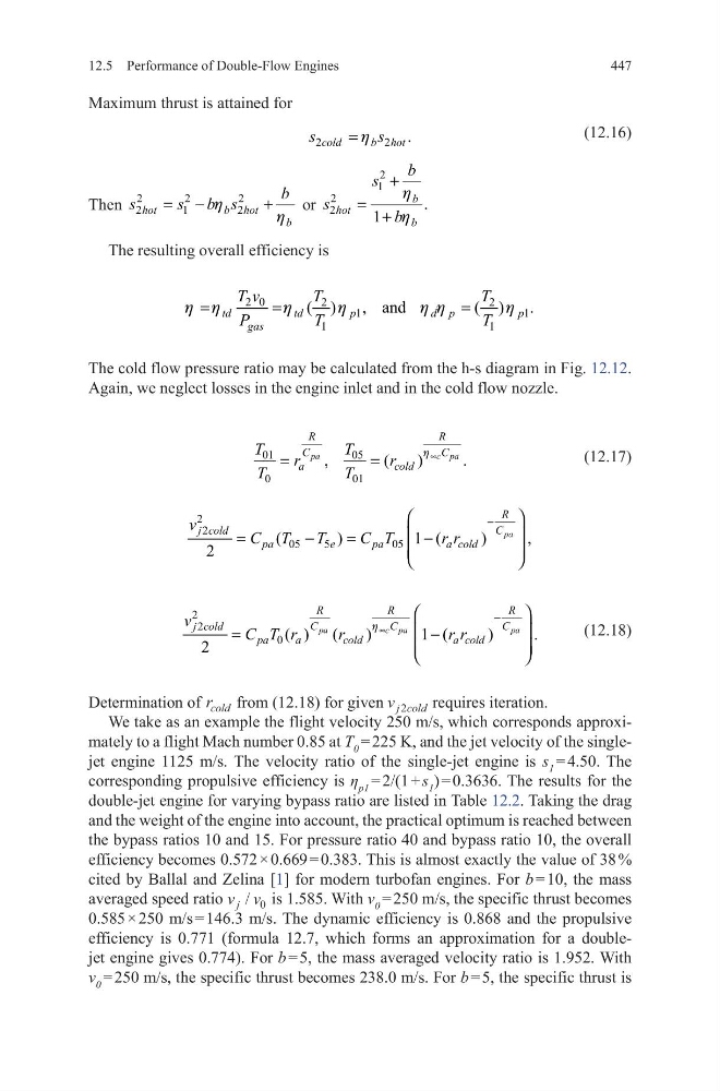
The cold flow pressure ratio may be calculated from the h-s diagram in Fig. 12.12.
Again, we neglect losses in the engine inlet and in the cold flow nozzle.
(12.17)
(12.18)
Determination of r cold from (12.18) for given v j cold
2
requires iteration.
We take as an example the flight velocity 250 m/s, which corresponds approximately to a flight Mach number 0.85 at T 0 = 225 K, and the jet velocity of the singlejet engine 1125 m/s. The velocity ratio of the single-jet engine is s 1 = 4.50. The
corresponding propulsive efficiency is η p1 = 2/(1 + s 1 ) = 0.3636. The results for the
double-jet engine for varying bypass ratio are listed in Table 12.2. Taking the drag
and the weight of the engine into account, the practical optimum is reached between
the bypass ratios 10 and 15. For pressure ratio 40 and bypass ratio 10, the overall
efficiency becomes 0.572 × 0.669 = 0.383. This is almost exactly the value of 38 %
cited by Ballal and Zelina [1] for modern turbofan engines. For b = 10, the mass
averaged speed ratio v v
j / 0 is 1.585. With v 0 = 250 m/s, the specific thrust becomes
0.585 × 250 m/s = 146.3 m/s. The dynamic efficiency is 0.868 and the propulsive
efficiency is 0.771 (formula 12.7, which forms an approximation for a doublejet engine gives 0.774). For b = 5, the mass averaged velocity ratio is 1.952. With
v 0 = 250 m/s, the specific thrust becomes 238.0 m/s. For b = 5, the specific thrust is
2
2
.
cold
b hot
s
s
h
=
2 0
2
2
1
1
1
1
( )
, and
( )
.
td
td
p
d p
p
gas
T v
T
T
P
T
T
h h
h
h
h h
h
=
=
=
01
05
0
01
,
(
)
.
pa
c pa
R
R
C
C
a
cold
T
T
r
r
T
T
h ∞
=
=
2
2
05
5
05
(
)
1 (
)
,
2
pa
R
C
j cold
pa
e
pa
a cold
v
C T
T
C T
r r
−
=
−
=
−
2
2
0 ( ) (
)
1 (
)
.
2
pa
c pa
pa
R
R
R
C
C
C
j cold
pa
a
cold
a cold
v
C T r
r
r r
h ∞
−
=
−
12.5 Performance of Double-Flow Engines
Maximum thrust is attained for
(12.16)
Then
2
2
2
2
1
2
hot
b hot
b
b
s
s b s
h
h
= −
+
or
2
1
2
2
.
1
b
hot
b
b
s
s
b
h
h
+
= +
The resulting overall efficiency is
The cold flow pressure ratio may be calculated from the h-s diagram in Fig. 12.12.
Again, we neglect losses in the engine inlet and in the cold flow nozzle.
(12.17)
(12.18)
Determination of r cold from (12.18) for given v j cold
2
requires iteration.
We take as an example the flight velocity 250 m/s, which corresponds approximately to a flight Mach number 0.85 at T 0 = 225 K, and the jet velocity of the singlejet engine 1125 m/s. The velocity ratio of the single-jet engine is s 1 = 4.50. The
corresponding propulsive efficiency is η p1 = 2/(1 + s 1 ) = 0.3636. The results for the
double-jet engine for varying bypass ratio are listed in Table 12.2. Taking the drag
and the weight of the engine into account, the practical optimum is reached between
the bypass ratios 10 and 15. For pressure ratio 40 and bypass ratio 10, the overall
efficiency becomes 0.572 × 0.669 = 0.383. This is almost exactly the value of 38 %
cited by Ballal and Zelina [1] for modern turbofan engines. For b = 10, the mass
averaged speed ratio v v
j / 0 is 1.585. With v 0 = 250 m/s, the specific thrust becomes
0.585 × 250 m/s = 146.3 m/s. The dynamic efficiency is 0.868 and the propulsive
efficiency is 0.771 (formula 12.7, which forms an approximation for a doublejet engine gives 0.774). For b = 5, the mass averaged velocity ratio is 1.952. With
v 0 = 250 m/s, the specific thrust becomes 238.0 m/s. For b = 5, the specific thrust is
2
2
.
cold
b hot
s
s
h
=
2 0
2
2
1
1
1
1
( )
, and
( )
.
td
td
p
d p
p
gas
T v
T
T
P
T
T
h h
h
h
h h
h
=
=
=
01
05
0
01
,
(
)
.
pa
c pa
R
R
C
C
a
cold
T
T
r
r
T
T
h ∞
=
=
2
2
05
5
05
(
)
1 (
)
,
2
pa
R
C
j cold
pa
e
pa
a cold
v
C T
T
C T
r r
−
=
−
=
−
2
2
0 ( ) (
)
1 (
)
.
2
pa
c pa
pa
R
R
R
C
C
C
j cold
pa
a
cold
a cold
v
C T r
r
r r
h ∞
−
=
−