

400
11 Power Gas Turbines
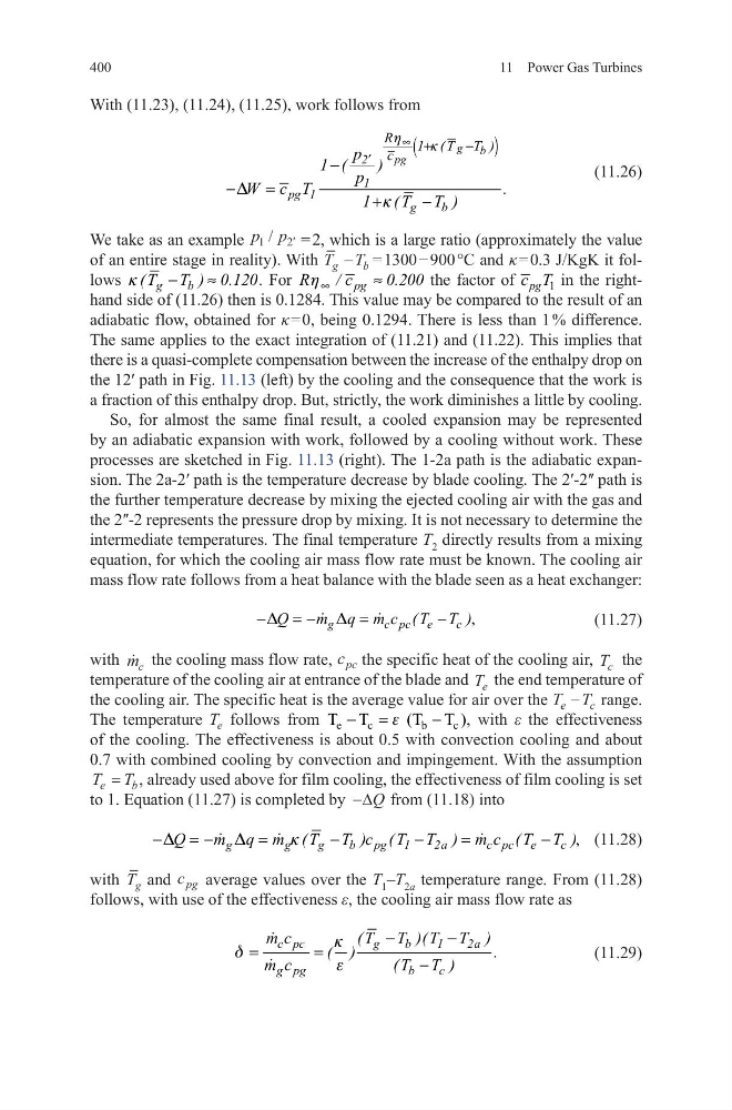
With (11.23), (11.24), (11.25), work follows from
(11.26)
We take as an example p p
1
2
/ ′ = 2, which is a large ratio (approximately the value
of an entire stage in reality). With T T
g
b
− = 1300 − 900 °C and κ = 0.3 J/KgK it follows
g
b
( T T ) 0.120
k
−
≈
. For
pg
R
/ c
0.200
h ∞
≈
the factor of
1
pg
c T in the righthand side of (11.26) then is 0.1284. This value may be compared to the result of an
adiabatic flow, obtained for κ = 0, being 0.1294. There is less than 1 % difference.
The same applies to the exact integration of (11.21) and (11.22). This implies that
there is a quasi-complete compensation between the increase of the enthalpy drop on
the 12ʹ path in Fig. 11.13 (left) by the cooling and the consequence that the work is
a fraction of this enthalpy drop. But, strictly, the work diminishes a little by cooling.
So, for almost the same final result, a cooled expansion may be represented
by an adiabatic expansion with work, followed by a cooling without work. These
processes are sketched in Fig. 11.13 (right). The 1-2a path is the adiabatic expansion. The 2a-2ʹ path is the temperature decrease by blade cooling. The 2ʹ-2ʺ path is
the further temperature decrease by mixing the ejected cooling air with the gas and
the 2ʺ-2 represents the pressure drop by mixing. It is not necessary to determine the
intermediate temperatures. The final temperature T 2 directly results from a mixing
equation, for which the cooling air mass flow rate must be known. The cooling air
mass flow rate follows from a heat balance with the blade seen as a heat exchanger:
(11.27)
with
m c the cooling mass flow rate, c pc the specific heat of the cooling air, T c the
temperature of the cooling air at entrance of the blade and T e the end temperature of
the cooling air. The specific heat is the average value for air over the T T
e
c
− range.
The temperature T e follows from e
c
b
c
T T
(T T )
e
− =
−
, with ε the effectiveness
of the cooling. The effectiveness is about 0.5 with convection cooling and about
0.7 with combined cooling by convection and impingement. With the assumption
T T
e
b
= , already used above for film cooling, the effectiveness of film cooling is set
to 1. Equation (11.27) is completed by −∆Q from (11.18) into
(11.28)
with T g and c pg average values over the T 1 –T 2a temperature range. From (11.28)
follows, with use of the effectiveness ε, the cooling air mass flow rate as
(11.29)
(
)
g b
pg
2
1
pg 1
g
b
R
1 ( T T )
c
p
1 (
)
p
W c T
.
1 (T T )
h
k
D
k
∞
′
+
−
−
−
=
+
−
,
g
c pc e
c
Q
m q m c (T T )
D
D
−
= −
=
−
,
g
g
g
b pg 1
2a
c pc e
c
Q
m q m (T T )c (T T ) m c (T T )
D
D
k
−
= −
=
−
−
=
−
c pc
g
b
1
2a
g pg
b
c
m c
(T T )(T T )
( )
.
m c
(T T )
k
d
e
−
−
=
=
−
11 Power Gas Turbines
With (11.23), (11.24), (11.25), work follows from
(11.26)
We take as an example p p
1
2
/ ′ = 2, which is a large ratio (approximately the value
of an entire stage in reality). With T T
g
b
− = 1300 − 900 °C and κ = 0.3 J/KgK it follows
g
b
( T T ) 0.120
k
−
≈
. For
pg
R
/ c
0.200
h ∞
≈
the factor of
1
pg
c T in the righthand side of (11.26) then is 0.1284. This value may be compared to the result of an
adiabatic flow, obtained for κ = 0, being 0.1294. There is less than 1 % difference.
The same applies to the exact integration of (11.21) and (11.22). This implies that
there is a quasi-complete compensation between the increase of the enthalpy drop on
the 12ʹ path in Fig. 11.13 (left) by the cooling and the consequence that the work is
a fraction of this enthalpy drop. But, strictly, the work diminishes a little by cooling.
So, for almost the same final result, a cooled expansion may be represented
by an adiabatic expansion with work, followed by a cooling without work. These
processes are sketched in Fig. 11.13 (right). The 1-2a path is the adiabatic expansion. The 2a-2ʹ path is the temperature decrease by blade cooling. The 2ʹ-2ʺ path is
the further temperature decrease by mixing the ejected cooling air with the gas and
the 2ʺ-2 represents the pressure drop by mixing. It is not necessary to determine the
intermediate temperatures. The final temperature T 2 directly results from a mixing
equation, for which the cooling air mass flow rate must be known. The cooling air
mass flow rate follows from a heat balance with the blade seen as a heat exchanger:
(11.27)
with
m c the cooling mass flow rate, c pc the specific heat of the cooling air, T c the
temperature of the cooling air at entrance of the blade and T e the end temperature of
the cooling air. The specific heat is the average value for air over the T T
e
c
− range.
The temperature T e follows from e
c
b
c
T T
(T T )
e
− =
−
, with ε the effectiveness
of the cooling. The effectiveness is about 0.5 with convection cooling and about
0.7 with combined cooling by convection and impingement. With the assumption
T T
e
b
= , already used above for film cooling, the effectiveness of film cooling is set
to 1. Equation (11.27) is completed by −∆Q from (11.18) into
(11.28)
with T g and c pg average values over the T 1 –T 2a temperature range. From (11.28)
follows, with use of the effectiveness ε, the cooling air mass flow rate as
(11.29)
(
)
g b
pg
2
1
pg 1
g
b
R
1 ( T T )
c
p
1 (
)
p
W c T
.
1 (T T )
h
k
D
k
∞
′
+
−
−
−
=
+
−
,
g
c pc e
c
Q
m q m c (T T )
D
D
−
= −
=
−
,
g
g
g
b pg 1
2a
c pc e
c
Q
m q m (T T )c (T T ) m c (T T )
D
D
k
−
= −
=
−
−
=
−
c pc
g
b
1
2a
g pg
b
c
m c
(T T )(T T )
( )
.
m c
(T T )
k
d
e
−
−
=
=
−