

15
Formula (1.11) also defines the relation between time differentiation in the relative
frame and time differentiation in the absolute frame for any vector quantity as this
may be considered being proportional to the difference of two coordinate vectors.
The differentiation rule applied to the velocity relation (1.10) results in:
where
a and
a rel respectively represent the absolute and the relative accelerations.
The basic laws may thus be applied in the relative frame, on condition of the
introduction of the (so-called) fictitious forces (per mass unit):
Centrifugal force:
2
Cf
(
r )
(
r ' )
r '
W W
W W
W
= − ×
× = − ×
×
=
,
Coriolis force:
Co
2
w
W
= − ×
,
where
′
r represents the radial distance vector of point P with respect to the axis of
rotation. From now on, this radial vector will be denoted by
r , as in a cylindrical
coordinate system.
An additional term comes in the right-hand part of the momentum equation:
Here, we applied dx1 1 dr
x r
. = and u
r
W
=
represents the blade speed. The Coriolis
force does not contribute to the work on the streamline.
From multiplication by the velocity and division by the mass flow rate it follows
that the additional term in the right-hand part of the work equation makes d u
2
/2,
with as a consequence
(1.12)
In other words, there is a centrifugal force contribution to the work on the streamline. The same contribution has to be added in the energy equation.
rel
d v
r
w
a
(
r )
w
(
r ) 2
w a ,
dt
dt
dt
d
d
W W
W
W
W W
W
=
= ×
× + × + ×
+
= ×
× +
× +
2
2
2
2
2
x
r
u
Adx r .1
A rdr
A d
Ad
.
2
2
r
W
r W
r W
r
=
=
=
2
2
1
1
irr
2
2
1
d w
dp dU dq
dW d u .
r
+
+
+
=
+
1.5 Basic Laws for Rotating Duct Parts
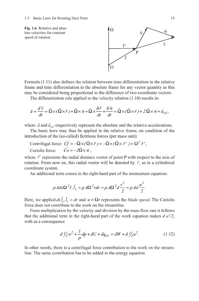
Fig. 1.6 Relative and absolute velocities for constant
speed of rotation
Formula (1.11) also defines the relation between time differentiation in the relative
frame and time differentiation in the absolute frame for any vector quantity as this
may be considered being proportional to the difference of two coordinate vectors.
The differentiation rule applied to the velocity relation (1.10) results in:
where
a and
a rel respectively represent the absolute and the relative accelerations.
The basic laws may thus be applied in the relative frame, on condition of the
introduction of the (so-called) fictitious forces (per mass unit):
Centrifugal force:
2
Cf
(
r )
(
r ' )
r '
W W
W W
W
= − ×
× = − ×
×
=
,
Coriolis force:
Co
2
w
W
= − ×
,
where
′
r represents the radial distance vector of point P with respect to the axis of
rotation. From now on, this radial vector will be denoted by
r , as in a cylindrical
coordinate system.
An additional term comes in the right-hand part of the momentum equation:
Here, we applied dx1 1 dr
x r
. = and u
r
W
=
represents the blade speed. The Coriolis
force does not contribute to the work on the streamline.
From multiplication by the velocity and division by the mass flow rate it follows
that the additional term in the right-hand part of the work equation makes d u
2
/2,
with as a consequence
(1.12)
In other words, there is a centrifugal force contribution to the work on the streamline. The same contribution has to be added in the energy equation.
rel
d v
r
w
a
(
r )
w
(
r ) 2
w a ,
dt
dt
dt
d
d
W W
W
W
W W
W
=
= ×
× + × + ×
+
= ×
× +
× +
2
2
2
2
2
x
r
u
Adx r .1
A rdr
A d
Ad
.
2
2
r
W
r W
r W
r
=
=
=
2
2
1
1
irr
2
2
1
d w
dp dU dq
dW d u .
r
+
+
+
=
+
1.5 Basic Laws for Rotating Duct Parts
Fig. 1.6 Relative and absolute velocities for constant
speed of rotation