

14
1 Working Principles
force occurs. Thus, denoting the heat transferred through the duct wall towards the
fluid by dq, the heat transferred through the envelope of the control volume equals
dq irr + dq. The energy law thus has dW - dq irr + dq irr + dq as its right-hand part, with
the second term representing the friction force work and the third term representing
the heat generated by dissipation. The resulting energy equation is the same as the
one with the first choice of the control volume.
The reasoning becomes more complex for a streamtube part within the fluid,
without a control volume envelope coinciding with a material wall. The product of
the friction force and the flow velocity then no longer corresponds to the work dissipated into heat. In other words, this work may contain an active part. In Chap. 2,
we will demonstrate that the work equation in form (1.5) and the energy equation
in form (1.7) stay valid for an arbitrary infinitesimal part of a streamline within a
steady flow. But, the general validity of the energy equation (1.7) is obvious on
the basis of the first law of thermodynamics, if one accepts that a part of the work
dW may be due to friction forces. However, quantifying that work and the heat dq
transferred to the fluid originating from the dissipation on the nearby streamlines
might be difficult. The general validity of the work equation (1.5) is, in the same
way, obvious on the basis of the second law of thermodynamics, but again a problem might arise in quantifying the active and the dissipative parts of the work. This
is further discussed in Chap. 2.
1.5 Basic Laws for Rotating Duct Parts
1.5.1 Work and Energy Equations in a Rotating Frame
with Constant Angular Velocity
In a relative frame rotating at a constant angular velocity (
Ω ) with respect to an
absolute frame, the basic laws of mechanics and thermodynamics still hold, provided that two fictitious forces are introduced: centrifugal force and Coriolis force.
These follow from the relation between absolute and relative velocities according
to (Fig. 1.6):
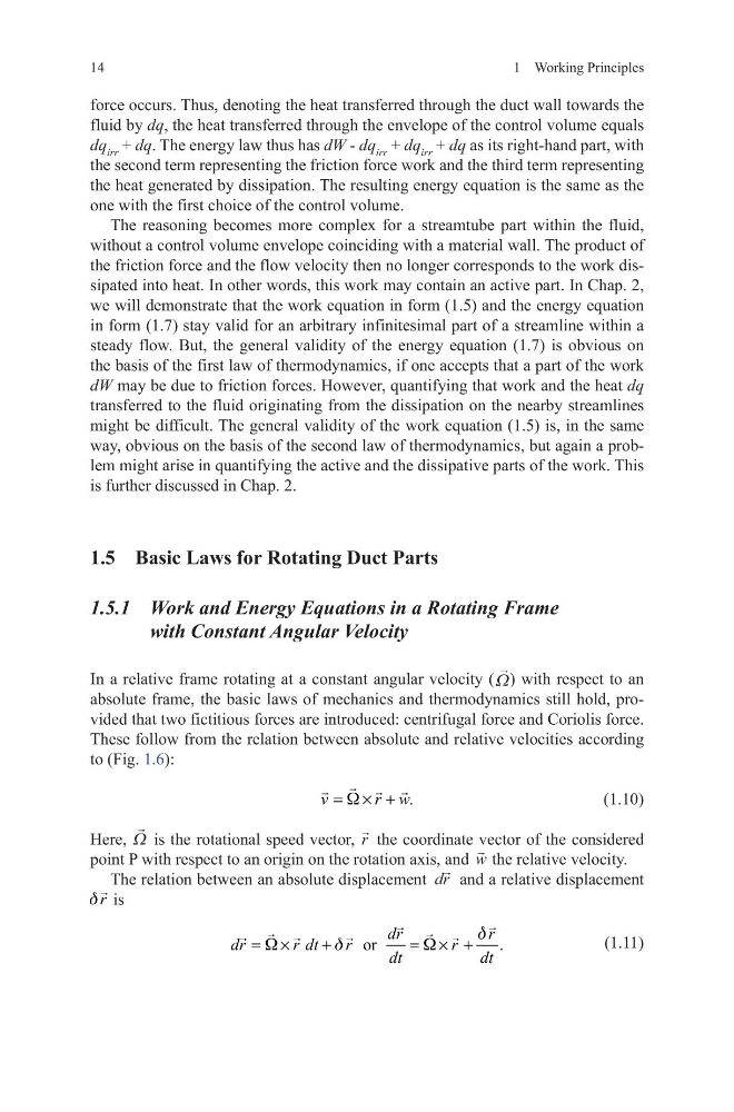
(1.10)
Here,
Ω is the rotational speed vector,
r the coordinate vector of the considered
point P with respect to an origin on the rotation axis, and
w the relative velocity.
The relation between an absolute displacement dr
and a relative displacement
r
d
is
(1.11)
v
r w.
W
= × +
or
dr
r
dr
r dt
r
r
.
dt
dt
d
W
d
W
= ×
+
= × +
1 Working Principles
force occurs. Thus, denoting the heat transferred through the duct wall towards the
fluid by dq, the heat transferred through the envelope of the control volume equals
dq irr + dq. The energy law thus has dW - dq irr + dq irr + dq as its right-hand part, with
the second term representing the friction force work and the third term representing
the heat generated by dissipation. The resulting energy equation is the same as the
one with the first choice of the control volume.
The reasoning becomes more complex for a streamtube part within the fluid,
without a control volume envelope coinciding with a material wall. The product of
the friction force and the flow velocity then no longer corresponds to the work dissipated into heat. In other words, this work may contain an active part. In Chap. 2,
we will demonstrate that the work equation in form (1.5) and the energy equation
in form (1.7) stay valid for an arbitrary infinitesimal part of a streamline within a
steady flow. But, the general validity of the energy equation (1.7) is obvious on
the basis of the first law of thermodynamics, if one accepts that a part of the work
dW may be due to friction forces. However, quantifying that work and the heat dq
transferred to the fluid originating from the dissipation on the nearby streamlines
might be difficult. The general validity of the work equation (1.5) is, in the same
way, obvious on the basis of the second law of thermodynamics, but again a problem might arise in quantifying the active and the dissipative parts of the work. This
is further discussed in Chap. 2.
1.5 Basic Laws for Rotating Duct Parts
1.5.1 Work and Energy Equations in a Rotating Frame
with Constant Angular Velocity
In a relative frame rotating at a constant angular velocity (
Ω ) with respect to an
absolute frame, the basic laws of mechanics and thermodynamics still hold, provided that two fictitious forces are introduced: centrifugal force and Coriolis force.
These follow from the relation between absolute and relative velocities according
to (Fig. 1.6):
(1.10)
Here,
Ω is the rotational speed vector,
r the coordinate vector of the considered
point P with respect to an origin on the rotation axis, and
w the relative velocity.
The relation between an absolute displacement dr
and a relative displacement
r
d
is
(1.11)
v
r w.
W
= × +
or
dr
r
dr
r dt
r
r
.
dt
dt
d
W
d
W
= ×
+
= × +