

359
10.3 Wind Turbine Performance Analysis
pressure difference p p
1
2
−
expresses the energy extraction from the flow. Downstream of the turbine, pressure increases again to p 0 , which decreases the velocity
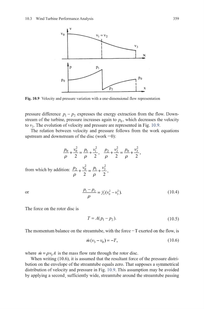
to v 3 . The evolution of velocity and pressure are represented in Fig. 10.9.
The relation between velocity and pressure follows from the work equations
upstream and downstream of the disc (work = 0):
from which by addition:
2
2
0
3
2
1
,
2
2
v
v
p
p
r
r
+
=
+
or
(10.4)
The force on the rotor disc is
(10.5)
The momentum balance on the streamtube, with the force − T exerted on the flow, is
(10.6)
where
1
m
v A
r
=
is the mass flow rate through the rotor disc.
When writing (10.6), it is assumed that the resultant force of the pressure distribution on the envelope of the streamtube equals zero. That supposes a symmetrical
distribution of velocity and pressure in Fig. 10.9. This assumption may be avoided
by applying a second¸ sufficiently wide, streamtube around the streamtube passing
2
2
2
2
0
0
0
3
1
1
2
2
,
,
2
2
2
2
p
v
p
v
p v
p
v
r
r
r
r
+
=
+
+
=
+
2
2
1
2
1 2
0
3
(
).
p p
v v
r
−
=
−
T A p p
=
−
(
) .
1
2
3
0
(
)
,
m v v
T
−
= −
Fig. 10.9 Velocity and pressure variation with a one-dimensional flow representation
10.3 Wind Turbine Performance Analysis
pressure difference p p
1
2
−
expresses the energy extraction from the flow. Downstream of the turbine, pressure increases again to p 0 , which decreases the velocity
to v 3 . The evolution of velocity and pressure are represented in Fig. 10.9.
The relation between velocity and pressure follows from the work equations
upstream and downstream of the disc (work = 0):
from which by addition:
2
2
0
3
2
1
,
2
2
v
v
p
p
r
r
+
=
+
or
(10.4)
The force on the rotor disc is
(10.5)
The momentum balance on the streamtube, with the force − T exerted on the flow, is
(10.6)
where
1
m
v A
r
=
is the mass flow rate through the rotor disc.
When writing (10.6), it is assumed that the resultant force of the pressure distribution on the envelope of the streamtube equals zero. That supposes a symmetrical
distribution of velocity and pressure in Fig. 10.9. This assumption may be avoided
by applying a second¸ sufficiently wide, streamtube around the streamtube passing
2
2
2
2
0
0
0
3
1
1
2
2
,
,
2
2
2
2
p
v
p
v
p v
p
v
r
r
r
r
+
=
+
+
=
+
2
2
1
2
1 2
0
3
(
).
p p
v v
r
−
=
−
T A p p
=
−
(
) .
1
2
3
0
(
)
,
m v v
T
−
= −
Fig. 10.9 Velocity and pressure variation with a one-dimensional flow representation