

349
10.2 Types of Wind Energy Conversion Systems
where P is the power produced by the machine, v 0 the undisturbed wind speed and A
is the through-flow area perpendicular to the wind direction. The through-flow area
is the area covered by the rotating parts of the machine. As already mentioned, and
as we will analyse further, the power coefficient of a modern lift-based wind energy
conversion system amounts to about 0.45. For a drag machine this is much lower,
typically around 0.20, due to large forces contrary to the sense of rotation and thus
dissipating energy. The third disadvantage with drag machines is their large solidity. The term solidity means the ratio of the blade surface to the through-flow area.
With drag machines, solidity typically exceeds unity. Drag machines are only rarely
applied and only for low-power applications. An example is the Savonius rotor on
the roof of vehicles to drive a fan in the interior.
10.2.2 High-Speed Horizontal-Axis Turbines
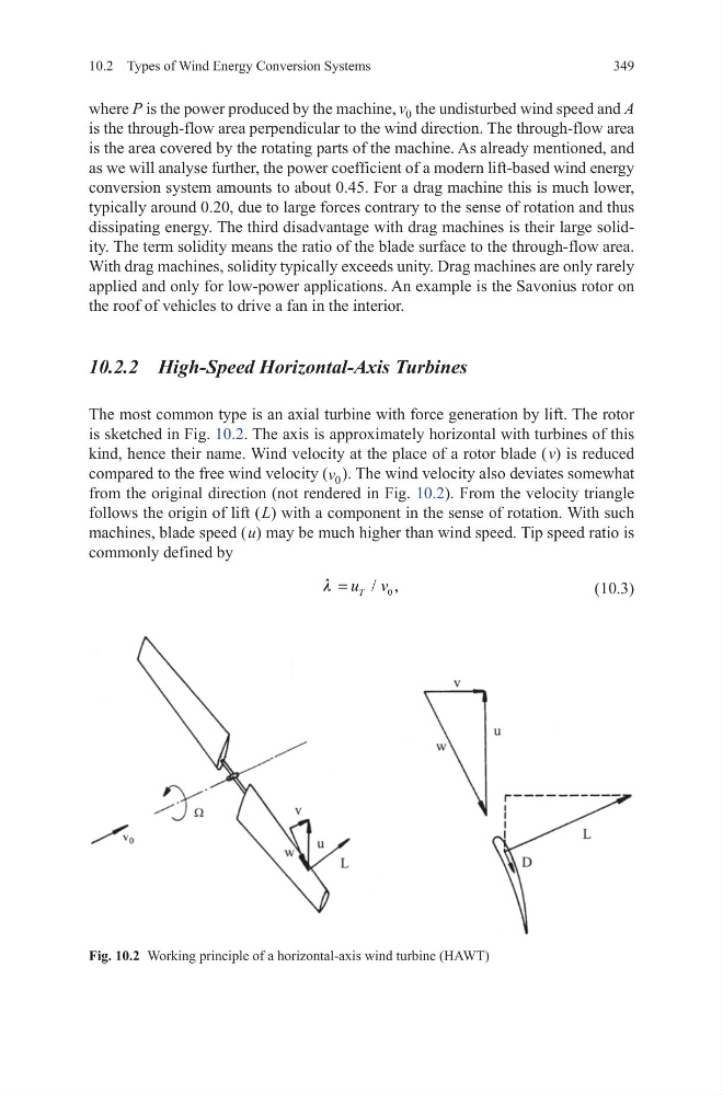
The most common type is an axial turbine with force generation by lift. The rotor
is sketched in Fig. 10.2. The axis is approximately horizontal with turbines of this
kind, hence their name. Wind velocity at the place of a rotor blade ( v) is reduced
compared to the free wind velocity (v 0 ). The wind velocity also deviates somewhat
from the original direction (not rendered in Fig. 10.2). From the velocity triangle
follows the origin of lift ( L) with a component in the sense of rotation. With such
machines, blade speed ( u) may be much higher than wind speed. Tip speed ratio is
commonly defined by
(10.3)
0
/ ,
T
u v
l =
Fig. 10.2 Working principle of a horizontal-axis wind turbine (HAWT)
10.2 Types of Wind Energy Conversion Systems
where P is the power produced by the machine, v 0 the undisturbed wind speed and A
is the through-flow area perpendicular to the wind direction. The through-flow area
is the area covered by the rotating parts of the machine. As already mentioned, and
as we will analyse further, the power coefficient of a modern lift-based wind energy
conversion system amounts to about 0.45. For a drag machine this is much lower,
typically around 0.20, due to large forces contrary to the sense of rotation and thus
dissipating energy. The third disadvantage with drag machines is their large solidity. The term solidity means the ratio of the blade surface to the through-flow area.
With drag machines, solidity typically exceeds unity. Drag machines are only rarely
applied and only for low-power applications. An example is the Savonius rotor on
the roof of vehicles to drive a fan in the interior.
10.2.2 High-Speed Horizontal-Axis Turbines
The most common type is an axial turbine with force generation by lift. The rotor
is sketched in Fig. 10.2. The axis is approximately horizontal with turbines of this
kind, hence their name. Wind velocity at the place of a rotor blade ( v) is reduced
compared to the free wind velocity (v 0 ). The wind velocity also deviates somewhat
from the original direction (not rendered in Fig. 10.2). From the velocity triangle
follows the origin of lift ( L) with a component in the sense of rotation. With such
machines, blade speed ( u) may be much higher than wind speed. Tip speed ratio is
commonly defined by
(10.3)
0
/ ,
T
u v
l =
Fig. 10.2 Working principle of a horizontal-axis wind turbine (HAWT)