

9.6 Reversible Pump-Turbines
341
motor-generator). The disadvantage of the three-machine combination is that the
pump is idling during turbine operation, and vice-versa. This disadvantage may be
avoided by disconnecting either the turbine or the pump. In practice, only the pump
shaft is provided with a coupling, as the pump has much more friction loss than the
turbine (the pump is typically multistage and the turbine is single-stage). The common shaft of the three machines may be mounted either horizontally or vertically.
With a vertical shaft, the electric machine is at the top, the turbine in the middle and
the pump at the bottom. This is in view of the priming of the pump and its larger
sensitivity to cavitation. With a combined motor-generator and a combined pumpturbine, two machines are sufficient for the pumped storage plant. The main advantage is then saving of investment cost (25–40 % on machines and 20–30 % on the
whole plant). The design of a rotor that can be efficient both for a turbine and for a
pump is not obvious, however. The discussion of bulb turbines already revealed that
an axial hydraulic machine may function both as a turbine and as a pump. The same
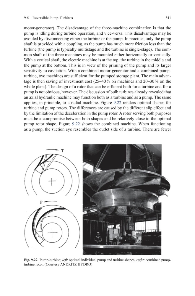
applies, in principle, to a radial machine. Figure 9.22 renders optimal shapes for
turbine and pump rotors. The differences are caused by the different slip effect and
by the limitation of the deceleration in the pump rotor. A rotor serving both purposes
must be a compromise between both shapes and be relatively close to the optimal
pump rotor shape. Figure 9.22 shows the combined machine. When functioning
as a pump, the suction eye resembles the outlet side of a turbine. There are fewer
Fig. 9.22 Pump-turbine; left: optimal individual pump and turbine shapes; right: combined pumpturbine rotor. (Courtesy ANDRITZ HYDRO)
341
motor-generator). The disadvantage of the three-machine combination is that the
pump is idling during turbine operation, and vice-versa. This disadvantage may be
avoided by disconnecting either the turbine or the pump. In practice, only the pump
shaft is provided with a coupling, as the pump has much more friction loss than the
turbine (the pump is typically multistage and the turbine is single-stage). The common shaft of the three machines may be mounted either horizontally or vertically.
With a vertical shaft, the electric machine is at the top, the turbine in the middle and
the pump at the bottom. This is in view of the priming of the pump and its larger
sensitivity to cavitation. With a combined motor-generator and a combined pumpturbine, two machines are sufficient for the pumped storage plant. The main advantage is then saving of investment cost (25–40 % on machines and 20–30 % on the
whole plant). The design of a rotor that can be efficient both for a turbine and for a
pump is not obvious, however. The discussion of bulb turbines already revealed that
an axial hydraulic machine may function both as a turbine and as a pump. The same
applies, in principle, to a radial machine. Figure 9.22 renders optimal shapes for
turbine and pump rotors. The differences are caused by the different slip effect and
by the limitation of the deceleration in the pump rotor. A rotor serving both purposes
must be a compromise between both shapes and be relatively close to the optimal
pump rotor shape. Figure 9.22 shows the combined machine. When functioning
as a pump, the suction eye resembles the outlet side of a turbine. There are fewer
Fig. 9.22 Pump-turbine; left: optimal individual pump and turbine shapes; right: combined pumpturbine rotor. (Courtesy ANDRITZ HYDRO)