

9 Hydraulic Turbines
340
the rotor blades into a position that is approximately mirrored with respect to the
meridional plane and reversing the sense of rotation create pump operation in the
estuary-sea sense. The positions are shown on part c of Fig. 9.20. Starting from
these positions, turning the stator vanes and rotor blades about 180° and reversing
the rotation sense creates pump operation in the estuary-sea sense, as shown on part
d in Fig. 9.20. Note that pump operation is obtained as well with blade positions in
part a in Fig. 9.20, with a reverse sense of rotation. Pumping then occurs in the seaestuary sense. But leading edges and trailing edges are then not adapted to the flow,
which strongly impairs the efficiency. Pump operation as sketched in parts c and d
of the figure is somewhat less efficient than the original turbine operation. The torsion of the blades is fixed. Blades may be positioned correctly for an average flow,
but positions are not fully correct for all streamtubes.
Pump operation also allows converting electric energy into hydraulic energy by
pumping water during periods of low electricity consumption. This then implies
functioning as a pumped storage plant. In France, the Rance tidal power/pumped
storage plant (near Mont Saint-Michel) was established according to this principle
(24 groups of 10 MW).
Small size plants (10–500 kW) use bulb turbines with an angled gearbox in the
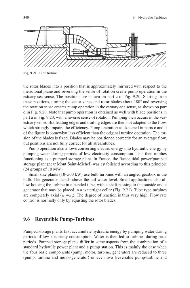
bulb. The generator stands above the tail water level. Small applications also allow housing the turbine in a bended tube, with a shaft passing to the outside and a
generator that may be placed in a watertight cellar (Fig. 9.21). Tube type turbines
are completely axial ( u 1 = u 2 ). The degree of reaction is thus very high. Flow rate
control is normally only by adjusting the rotor blades.
9.6 Reversible Pump-Turbines
Pumped storage plants first accumulate hydraulic energy by pumping water during
periods of low electricity consumption. Water is then led to turbines during peak
periods. Pumped storage plants differ in some aspects from the combination of a
standard hydraulic power plant and a pump station. This is mainly the case when
the four basic components (pump, motor, turbine, generator) are reduced to three
(pump, turbine and motor-generator) or even two (reversible pump-turbine and
Fig. 9.21 Tube turbine
340
the rotor blades into a position that is approximately mirrored with respect to the
meridional plane and reversing the sense of rotation create pump operation in the
estuary-sea sense. The positions are shown on part c of Fig. 9.20. Starting from
these positions, turning the stator vanes and rotor blades about 180° and reversing
the rotation sense creates pump operation in the estuary-sea sense, as shown on part
d in Fig. 9.20. Note that pump operation is obtained as well with blade positions in
part a in Fig. 9.20, with a reverse sense of rotation. Pumping then occurs in the seaestuary sense. But leading edges and trailing edges are then not adapted to the flow,
which strongly impairs the efficiency. Pump operation as sketched in parts c and d
of the figure is somewhat less efficient than the original turbine operation. The torsion of the blades is fixed. Blades may be positioned correctly for an average flow,
but positions are not fully correct for all streamtubes.
Pump operation also allows converting electric energy into hydraulic energy by
pumping water during periods of low electricity consumption. This then implies
functioning as a pumped storage plant. In France, the Rance tidal power/pumped
storage plant (near Mont Saint-Michel) was established according to this principle
(24 groups of 10 MW).
Small size plants (10–500 kW) use bulb turbines with an angled gearbox in the
bulb. The generator stands above the tail water level. Small applications also allow housing the turbine in a bended tube, with a shaft passing to the outside and a
generator that may be placed in a watertight cellar (Fig. 9.21). Tube type turbines
are completely axial ( u 1 = u 2 ). The degree of reaction is thus very high. Flow rate
control is normally only by adjusting the rotor blades.
9.6 Reversible Pump-Turbines
Pumped storage plants first accumulate hydraulic energy by pumping water during
periods of low electricity consumption. Water is then led to turbines during peak
periods. Pumped storage plants differ in some aspects from the combination of a
standard hydraulic power plant and a pump station. This is mainly the case when
the four basic components (pump, motor, turbine, generator) are reduced to three
(pump, turbine and motor-generator) or even two (reversible pump-turbine and
Fig. 9.21 Tube turbine