

9.4 Francis and Kaplan Turbines: Reaction Turbines
331
that, but the required outlet area then increases. We therefore provisionally assume
the ratio as 1, but we keep in mind that a reduction is advantageous, if feasible. The
velocity ratio w w
2
1
/
,
= 1 principally, is not optimal. If, at given v 2m , acceleration is
incorporated, the flow turning in the rotor increases. This implies an increase of the
work by the lift force. Work by the Coriolis force equals u u
1
2
2
2
− . The work by lift
force equals u w
u w
u
u
1 1
2 2
−
. Note that the lift work is negative with the triangles in
Fig. 9.10. It may be made less negative, even positive, by incorporating acceleration. This enables a reduction of the number of blades, resulting in a smaller friction
surface. A greater turning increases the rotor loss coefficient, however, and greater
outlet velocity increases losses as well. Thus, acceleration and turning should not be
too big. Incorporating some acceleration in order to prevent a negative contribution
to the work by the lift force, even making it somewhat positive, is thus advantageous.
9.4.3 Degree of Reaction and Speed Ratio
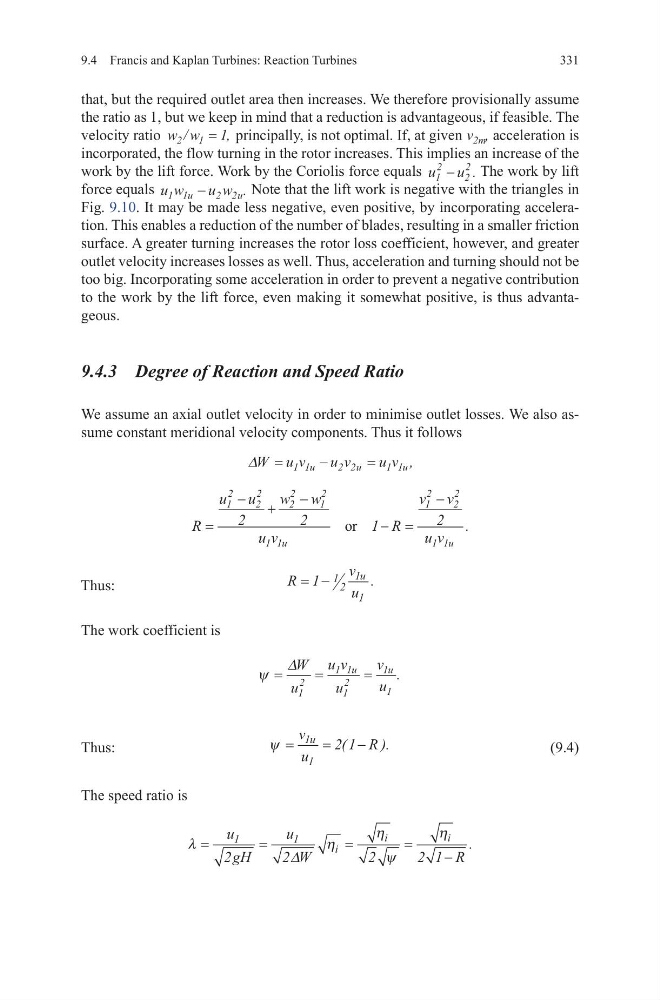
We assume an axial outlet velocity in order to minimise outlet losses. We also assume constant meridional velocity components. Thus it follows
Thus:
The work coefficient is
Thus:
(9.4)
The speed ratio is
∆W u v
u v
u v
u
u
u
=
−
=
1 1
2 2
1 1 ,
R
u u
w w
u v
R
v v
u v
u
u
=
− +
−
− =
−
1
2
2
2
2
2
1
2
1 1
1
2
2
2
1 1
2
2
1
2
or
.
R
v
u
u
= −
1 1 2
1
1
.
ψ =
=
=
∆W
u
u v
u
v
u
u
u
1
2
1 1
1
2
1
1
.
ψ =
=
−
v
u
R
u
1
1
2 1
(
).
λ
η
η
ψ
η
=
=
=
=
−
u
gH
u
W
R
i
i
i
1
1
2
2
2
2 1
∆
.
331
that, but the required outlet area then increases. We therefore provisionally assume
the ratio as 1, but we keep in mind that a reduction is advantageous, if feasible. The
velocity ratio w w
2
1
/
,
= 1 principally, is not optimal. If, at given v 2m , acceleration is
incorporated, the flow turning in the rotor increases. This implies an increase of the
work by the lift force. Work by the Coriolis force equals u u
1
2
2
2
− . The work by lift
force equals u w
u w
u
u
1 1
2 2
−
. Note that the lift work is negative with the triangles in
Fig. 9.10. It may be made less negative, even positive, by incorporating acceleration. This enables a reduction of the number of blades, resulting in a smaller friction
surface. A greater turning increases the rotor loss coefficient, however, and greater
outlet velocity increases losses as well. Thus, acceleration and turning should not be
too big. Incorporating some acceleration in order to prevent a negative contribution
to the work by the lift force, even making it somewhat positive, is thus advantageous.
9.4.3 Degree of Reaction and Speed Ratio
We assume an axial outlet velocity in order to minimise outlet losses. We also assume constant meridional velocity components. Thus it follows
Thus:
The work coefficient is
Thus:
(9.4)
The speed ratio is
∆W u v
u v
u v
u
u
u
=
−
=
1 1
2 2
1 1 ,
R
u u
w w
u v
R
v v
u v
u
u
=
− +
−
− =
−
1
2
2
2
2
2
1
2
1 1
1
2
2
2
1 1
2
2
1
2
or
.
R
v
u
u
= −
1 1 2
1
1
.
ψ =
=
=
∆W
u
u v
u
v
u
u
u
1
2
1 1
1
2
1
1
.
ψ =
=
−
v
u
R
u
1
1
2 1
(
).
λ
η
η
ψ
η
=
=
=
=
−
u
gH
u
W
R
i
i
i
1
1
2
2
2
2 1
∆
.