

7 Dynamic Similitude
264
Here, h geo is the geometric height difference between the levels in the suction and
discharge reservoirs. The required energy rise as a function of the flow rate is denominated the load characteristic. Pump and load characteristics are sketched in
Fig. 7.11. The load characteristic has a static part, which is the value at zero flow
rate and a dynamic part which increases approximately with the square of the flow
rate. The dynamic part is typically denoted by the term head loss, meaning the dissipation of mechanical energy due to loss mechanisms. The intersection of both characteristics determines the operating point of the pump. When designing the installation, a pump with an optimum operating point close to the target operating point
should be chosen. Also, the pipe dimensions should be optimised in the sense that
a balance should be made between the energy cost by dissipation within the pipes
and the investment cost of the pipes, taking their expected life time into account. A
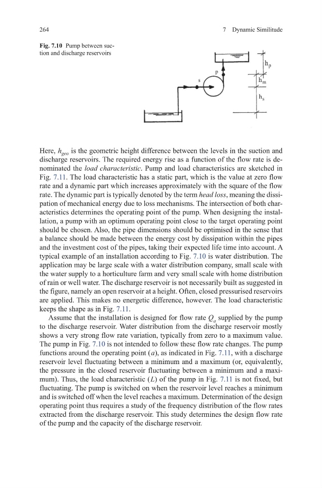
typical example of an installation according to Fig. 7.10 is water distribution. The
application may be large scale with a water distribution company, small scale with
the water supply to a horticulture farm and very small scale with home distribution
of rain or well water. The discharge reservoir is not necessarily built as suggested in
the figure, namely an open reservoir at a height. Often, closed pressurised reservoirs
are applied. This makes no energetic difference, however. The load characteristic
keeps the shape as in Fig. 7.11.
Assume that the installation is designed for flow rate Q a supplied by the pump
to the discharge reservoir. Water distribution from the discharge reservoir mostly
shows a very strong flow rate variation, typically from zero to a maximum value.
The pump in Fig. 7.10 is not intended to follow these flow rate changes. The pump
functions around the operating point ( a), as indicated in Fig. 7.11, with a discharge
reservoir level fluctuating between a minimum and a maximum (or, equivalently,
the pressure in the closed reservoir fluctuating between a minimum and a maximum). Thus, the load characteristic ( L) of the pump in Fig. 7.11 is not fixed, but
fluctuating. The pump is switched on when the reservoir level reaches a minimum
and is switched off when the level reaches a maximum. Determination of the design
operating point thus requires a study of the frequency distribution of the flow rates
extracted from the discharge reservoir. This study determines the design flow rate
of the pump and the capacity of the discharge reservoir.
s
p
p
h
s
h
m
h
Fig. 7.10 Pump between suction and discharge reservoirs
264
Here, h geo is the geometric height difference between the levels in the suction and
discharge reservoirs. The required energy rise as a function of the flow rate is denominated the load characteristic. Pump and load characteristics are sketched in
Fig. 7.11. The load characteristic has a static part, which is the value at zero flow
rate and a dynamic part which increases approximately with the square of the flow
rate. The dynamic part is typically denoted by the term head loss, meaning the dissipation of mechanical energy due to loss mechanisms. The intersection of both characteristics determines the operating point of the pump. When designing the installation, a pump with an optimum operating point close to the target operating point
should be chosen. Also, the pipe dimensions should be optimised in the sense that
a balance should be made between the energy cost by dissipation within the pipes
and the investment cost of the pipes, taking their expected life time into account. A
typical example of an installation according to Fig. 7.10 is water distribution. The
application may be large scale with a water distribution company, small scale with
the water supply to a horticulture farm and very small scale with home distribution
of rain or well water. The discharge reservoir is not necessarily built as suggested in
the figure, namely an open reservoir at a height. Often, closed pressurised reservoirs
are applied. This makes no energetic difference, however. The load characteristic
keeps the shape as in Fig. 7.11.
Assume that the installation is designed for flow rate Q a supplied by the pump
to the discharge reservoir. Water distribution from the discharge reservoir mostly
shows a very strong flow rate variation, typically from zero to a maximum value.
The pump in Fig. 7.10 is not intended to follow these flow rate changes. The pump
functions around the operating point ( a), as indicated in Fig. 7.11, with a discharge
reservoir level fluctuating between a minimum and a maximum (or, equivalently,
the pressure in the closed reservoir fluctuating between a minimum and a maximum). Thus, the load characteristic ( L) of the pump in Fig. 7.11 is not fixed, but
fluctuating. The pump is switched on when the reservoir level reaches a minimum
and is switched off when the level reaches a maximum. Determination of the design
operating point thus requires a study of the frequency distribution of the flow rates
extracted from the discharge reservoir. This study determines the design flow rate
of the pump and the capacity of the discharge reservoir.
s
p
p
h
s
h
m
h
Fig. 7.10 Pump between suction and discharge reservoirs