

243
6.10 Exercises
tribute as ∆h
h h
ss
s
= −
0
1 = 76.5 kJ/kg and ∆h
h
h
sr
s
s
=
−
1
2 = 8.5 kJ/kg. Calculate
the last stage without consideration of the recovery of the outlet kinetic energy
in the diffuser downstream of the last stage. This means that it is assumed that
the magnitude of the axial velocity downstream of the stage has been chosen
already. In reality, the optimisation of the outlet velocity determines the value of
the nozzle angle. So, it is assumed here that 1 70
°
=
a
is the result.
A: The calculations require iteration.
β
β
η
1
2
1
2
53 2
5 7 4
0 081
79 45
0 9
=
°
= −
° =
=
−
=
=
. ,
.
.
(
)
.
.
;
;
;
R
W u v
v
k J kg
u
u
tt
∆
3 35.
e. Determine the velocity triangles as a function of the radius, taking into
account: v u
1 ~r
a
−
,
2
1
1a
1u
1 1s
1 s
ss
1s
s
2
v
v tg ,v
v
, h
v , h
=
=
=
a
f D
D = 85 kJ/kg and
∆
∆
∆
h
h
h
sr
s
s s
=
−
. Take as inflow velocity of the stator the value of v a
2 at the
hub. Calculate loss coefficients with the formula of Soderberg, ignoring secondary loss. Take as approximation that v a
2 is constant along the radius. With this
last assumption, a mass flow balance is not necessary. This can be used afterwards to determine the height of the streamtubes at inlet and outlet of the rotor.
Calculate for the values of radius: r = 1.25, 1.60, 2.15 m, 3.00 m.
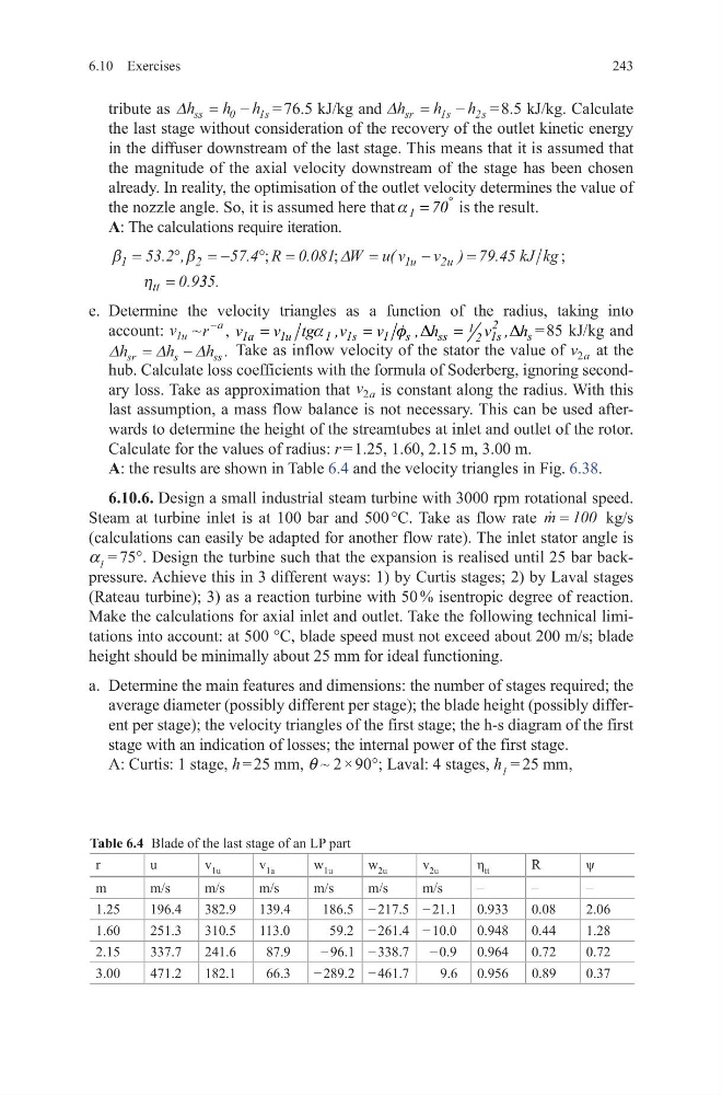
A: the results are shown in Table 6.4 and the velocity triangles in Fig. 6.38.
6.10.6. Design a small industrial steam turbine with 3000 rpm rotational speed.
Steam at turbine inlet is at 100 bar and 500 °C. Take as flow rate
m = 100 kg/s
(calculations can easily be adapted for another flow rate). The inlet stator angle is
a 1 = 75°. Design the turbine such that the expansion is realised until 25 bar backpressure. Achieve this in 3 different ways: 1) by Curtis stages; 2) by Laval stages
(Rateau turbine); 3) as a reaction turbine with 50 % isentropic degree of reaction.
Make the calculations for axial inlet and outlet. Take the following technical limitations into account: at 500 °C, blade speed must not exceed about 200 m/s; blade
height should be minimally about 25 mm for ideal functioning.
a. Determine the main features and dimensions: the number of stages required; the
average diameter (possibly different per stage); the blade height (possibly different per stage); the velocity triangles of the first stage; the h-s diagram of the first
stage with an indication of losses; the internal power of the first stage.
A: Curtis: 1 stage, h = 25 mm, q ~ 2 × 90°; Laval: 4 stages, h 1 = 25 mm,
Table 6.4 Blade of the last stage of an LP part
r
u
v 1u
v 1a
w 1u
w 2u
v 2u
η tt
R
ψ
m
m/s
m/s
m/s
m/s
m/s
m/s
–
–
–
1.25
196.4
382.9
139.4
186.5 − 217.5 − 21.1 0.933
0.08
2.06
1.60
251.3
310.5
113.0
59.2 − 261.4 − 10.0 0.948
0.44
1.28
2.15
337.7
241.6
87.9
− 96.1 − 338.7 − 0.9 0.964
0.72
0.72
3.00
471.2
182.1
66.3
− 289.2 − 461.7
9.6 0.956
0.89
0.37
6.10 Exercises
tribute as ∆h
h h
ss
s
= −
0
1 = 76.5 kJ/kg and ∆h
h
h
sr
s
s
=
−
1
2 = 8.5 kJ/kg. Calculate
the last stage without consideration of the recovery of the outlet kinetic energy
in the diffuser downstream of the last stage. This means that it is assumed that
the magnitude of the axial velocity downstream of the stage has been chosen
already. In reality, the optimisation of the outlet velocity determines the value of
the nozzle angle. So, it is assumed here that 1 70
°
=
a
is the result.
A: The calculations require iteration.
β
β
η
1
2
1
2
53 2
5 7 4
0 081
79 45
0 9
=
°
= −
° =
=
−
=
=
. ,
.
.
(
)
.
.
;
;
;
R
W u v
v
k J kg
u
u
tt
∆
3 35.
e. Determine the velocity triangles as a function of the radius, taking into
account: v u
1 ~r
a
−
,
2
1
1a
1u
1 1s
1 s
ss
1s
s
2
v
v tg ,v
v
, h
v , h
=
=
=
a
f D
D = 85 kJ/kg and
∆
∆
∆
h
h
h
sr
s
s s
=
−
. Take as inflow velocity of the stator the value of v a
2 at the
hub. Calculate loss coefficients with the formula of Soderberg, ignoring secondary loss. Take as approximation that v a
2 is constant along the radius. With this
last assumption, a mass flow balance is not necessary. This can be used afterwards to determine the height of the streamtubes at inlet and outlet of the rotor.
Calculate for the values of radius: r = 1.25, 1.60, 2.15 m, 3.00 m.
A: the results are shown in Table 6.4 and the velocity triangles in Fig. 6.38.
6.10.6. Design a small industrial steam turbine with 3000 rpm rotational speed.
Steam at turbine inlet is at 100 bar and 500 °C. Take as flow rate
m = 100 kg/s
(calculations can easily be adapted for another flow rate). The inlet stator angle is
a 1 = 75°. Design the turbine such that the expansion is realised until 25 bar backpressure. Achieve this in 3 different ways: 1) by Curtis stages; 2) by Laval stages
(Rateau turbine); 3) as a reaction turbine with 50 % isentropic degree of reaction.
Make the calculations for axial inlet and outlet. Take the following technical limitations into account: at 500 °C, blade speed must not exceed about 200 m/s; blade
height should be minimally about 25 mm for ideal functioning.
a. Determine the main features and dimensions: the number of stages required; the
average diameter (possibly different per stage); the blade height (possibly different per stage); the velocity triangles of the first stage; the h-s diagram of the first
stage with an indication of losses; the internal power of the first stage.
A: Curtis: 1 stage, h = 25 mm, q ~ 2 × 90°; Laval: 4 stages, h 1 = 25 mm,
Table 6.4 Blade of the last stage of an LP part
r
u
v 1u
v 1a
w 1u
w 2u
v 2u
η tt
R
ψ
m
m/s
m/s
m/s
m/s
m/s
m/s
–
–
–
1.25
196.4
382.9
139.4
186.5 − 217.5 − 21.1 0.933
0.08
2.06
1.60
251.3
310.5
113.0
59.2 − 261.4 − 10.0 0.948
0.44
1.28
2.15
337.7
241.6
87.9
− 96.1 − 338.7 − 0.9 0.964
0.72
0.72
3.00
471.2
182.1
66.3
− 289.2 − 461.7
9.6 0.956
0.89
0.37