

240
6 Steam Turbines
Both C Fu = 1 and D loc = 0 5
. lead to b r
/
.
2
0 5
< . In practice, the upper limit is taken as b r
/
. ,
2
0 4
=
leading to r
b
2
2 5
= . and r
b
1
1 5
= . . This means that the channel
width may be at maximum half of the radius of curvature of a mean streamline. This
rule is sometimes called Brilling’s rule [1].
The channel width becomes b = 23.09 mm, rounded to 23 mm. Taking the blade
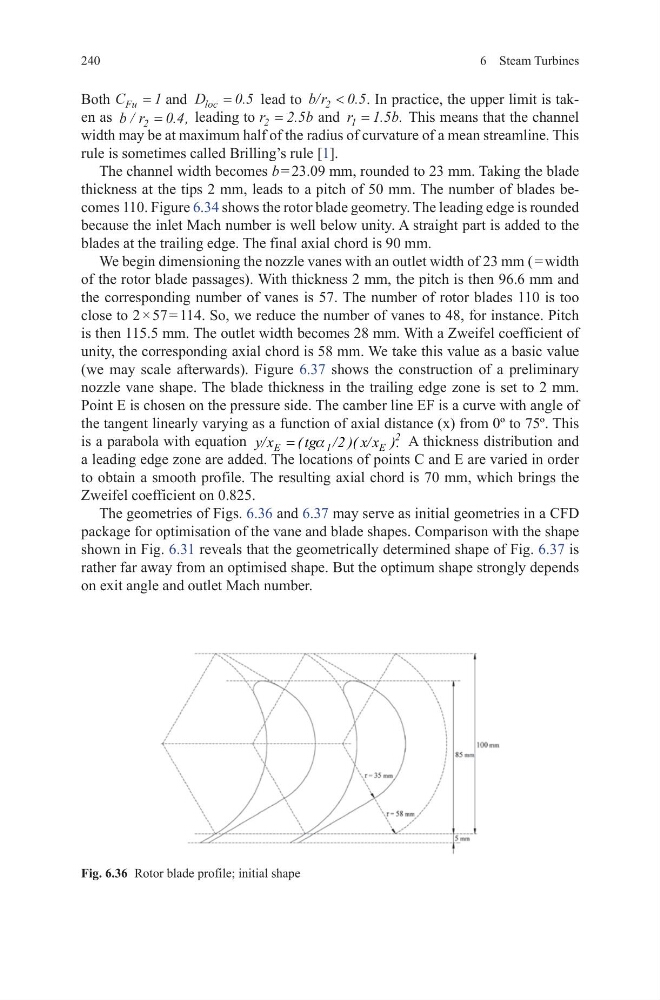
thickness at the tips 2 mm, leads to a pitch of 50 mm. The number of blades becomes 110. Figure 6.34 shows the rotor blade geometry. The leading edge is rounded
because the inlet Mach number is well below unity. A straight part is added to the
blades at the trailing edge. The final axial chord is 90 mm.
We begin dimensioning the nozzle vanes with an outlet width of 23 mm ( = width
of the rotor blade passages). With thickness 2 mm, the pitch is then 96.6 mm and
the corresponding number of vanes is 57. The number of rotor blades 110 is too
close to 2 × 57 = 114. So, we reduce the number of vanes to 48, for instance. Pitch
is then 115.5 mm. The outlet width becomes 28 mm. With a Zweifel coefficient of
unity, the corresponding axial chord is 58 mm. We take this value as a basic value
(we may scale afterwards). Figure 6.37 shows the construction of a preliminary
nozzle vane shape. The blade thickness in the trailing edge zone is set to 2 mm.
Point E is chosen on the pressure side. The camber line EF is a curve with angle of
the tangent linearly varying as a function of axial distance (x) from 0º to 75º. This
is a parabola with equation
2
E
1
E
y/x
( tg /2 )( x/x ).
= a
A thickness distribution and
a leading edge zone are added. The locations of points C and E are varied in order
to obtain a smooth profile. The resulting axial chord is 70 mm, which brings the
Zweifel coefficient on 0.825.
The geometries of Figs. 6.36 and 6.37 may serve as initial geometries in a CFD
package for optimisation of the vane and blade shapes. Comparison with the shape
shown in Fig. 6.31 reveals that the geometrically determined shape of Fig. 6.37 is
rather far away from an optimised shape. But the optimum shape strongly depends
on exit angle and outlet Mach number.
Fig. 6.36 Rotor blade profile; initial shape
6 Steam Turbines
Both C Fu = 1 and D loc = 0 5
. lead to b r
/
.
2
0 5
< . In practice, the upper limit is taken as b r
/
. ,
2
0 4
=
leading to r
b
2
2 5
= . and r
b
1
1 5
= . . This means that the channel
width may be at maximum half of the radius of curvature of a mean streamline. This
rule is sometimes called Brilling’s rule [1].
The channel width becomes b = 23.09 mm, rounded to 23 mm. Taking the blade
thickness at the tips 2 mm, leads to a pitch of 50 mm. The number of blades becomes 110. Figure 6.34 shows the rotor blade geometry. The leading edge is rounded
because the inlet Mach number is well below unity. A straight part is added to the
blades at the trailing edge. The final axial chord is 90 mm.
We begin dimensioning the nozzle vanes with an outlet width of 23 mm ( = width
of the rotor blade passages). With thickness 2 mm, the pitch is then 96.6 mm and
the corresponding number of vanes is 57. The number of rotor blades 110 is too
close to 2 × 57 = 114. So, we reduce the number of vanes to 48, for instance. Pitch
is then 115.5 mm. The outlet width becomes 28 mm. With a Zweifel coefficient of
unity, the corresponding axial chord is 58 mm. We take this value as a basic value
(we may scale afterwards). Figure 6.37 shows the construction of a preliminary
nozzle vane shape. The blade thickness in the trailing edge zone is set to 2 mm.
Point E is chosen on the pressure side. The camber line EF is a curve with angle of
the tangent linearly varying as a function of axial distance (x) from 0º to 75º. This
is a parabola with equation
2
E
1
E
y/x
( tg /2 )( x/x ).
= a
A thickness distribution and
a leading edge zone are added. The locations of points C and E are varied in order
to obtain a smooth profile. The resulting axial chord is 70 mm, which brings the
Zweifel coefficient on 0.825.
The geometries of Figs. 6.36 and 6.37 may serve as initial geometries in a CFD
package for optimisation of the vane and blade shapes. Comparison with the shape
shown in Fig. 6.31 reveals that the geometrically determined shape of Fig. 6.37 is
rather far away from an optimised shape. But the optimum shape strongly depends
on exit angle and outlet Mach number.
Fig. 6.36 Rotor blade profile; initial shape