

239
6.10 Exercises
reached by the rotational speed 3000 rpm. Such an arrangement, sometimes chosen by other manufacturers, requires two shafts driving each a generator (so-called
cross-compound machine).
Determine the number of stages in the HP part, assuming that the degree of reaction is 10 % at the hub and that the hub diameter is 1.75 m. Design the hub section
of the first stage of the HP part with zero degree of reaction (Laval stage). The real
machine has a small positive degree of reaction at the hub, but we take zero degree
of reaction for the ease of computation. Take 1 75 .
°
=
a
A: (
)
(
)
:
h
38kJ kg , h
340 kJ kg
s stage
s HP part
≈
≈
−
D
D
9 stages (see Fig. 6.26).
There is recovery of outlet kinetic energy of the stage. So, calculation of the velocity triangles requires iteration. Assuming a repeating stage and symmetrical rotor
blades, the velocity triangles result in 1
2
60.83 .
b
b
°
= − =
For determination of the
blade shape, according to Fig. 6.9, we take 1
2
60 .
b
b
°
= − =
We denote the inner and
outer radii of the blade channel by r 1 and r 2 and the channel width by b = r 2 –r 1 . The
height of the stator vanes at outlet = height of the rotor blades at inlet ≈ 183 mm.
We choose the axial chord of the rotor blades equal to 100 mm (we may scale afterwards) and the minimum blade thickness to 2 mm.
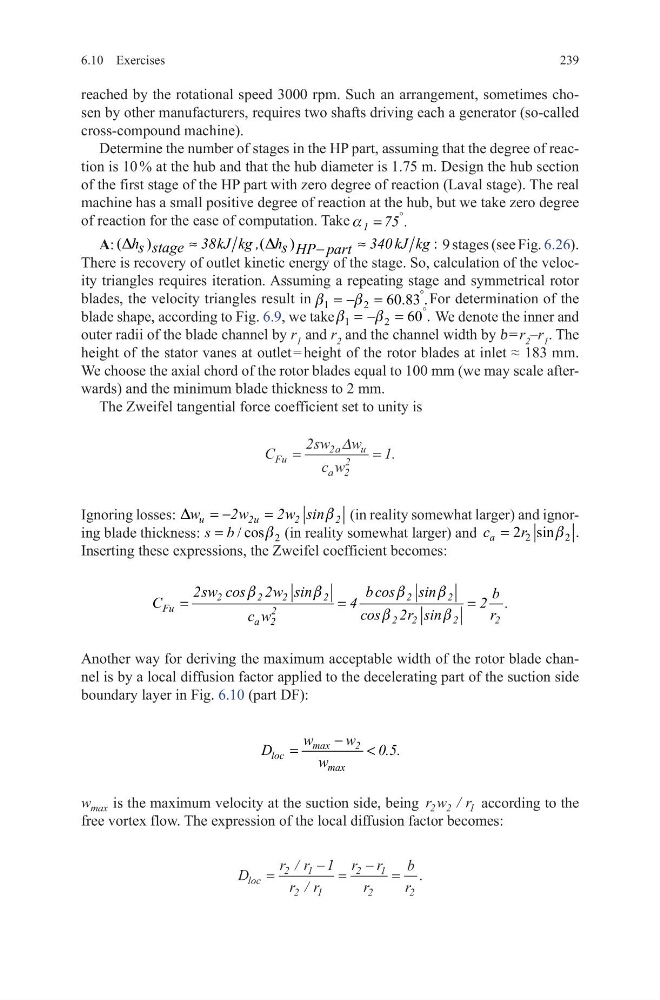
The Zweifel tangential force coefficient set to unity is
Ignoring losses:
u
2u
2
2
w
2w
2w sin
= −
=
D
b (in reality somewhat larger) and ignoring blade thickness:
2
/ cos
s b
b
=
(in reality somewhat larger) and
2
2
2 sin .
a
c
r
b
=
Inserting these expressions, the Zweifel coefficient becomes:
Another way for deriving the maximum acceptable width of the rotor blade channel is by a local diffusion factor applied to the decelerating part of the suction side
boundary layer in Fig. 6.10 (part DF):
w max is the maximum velocity at the suction side, being r w r
2 2
1
/ according to the
free vortex flow. The expression of the local diffusion factor becomes:
C
sw w
c w
Fu
a
u
a
=
=
2
1
2
2
2
∆
.
2
2
2
2
2
2
Fu
2
2 2
2
2
a 2
2sw cos 2w sin
b cos
sin
b
C
4
2 .
cos 2r sin
r
c w
=
=
=
b
b
b
b
b
b
max
2
loc
max
w
w
D
0.5.
w
−
=
<
D
r r
r r
r r
r
b
r
loc =
− =
− =
2
1
2
1
2
1
2
2
1
/
/
.
6.10 Exercises
reached by the rotational speed 3000 rpm. Such an arrangement, sometimes chosen by other manufacturers, requires two shafts driving each a generator (so-called
cross-compound machine).
Determine the number of stages in the HP part, assuming that the degree of reaction is 10 % at the hub and that the hub diameter is 1.75 m. Design the hub section
of the first stage of the HP part with zero degree of reaction (Laval stage). The real
machine has a small positive degree of reaction at the hub, but we take zero degree
of reaction for the ease of computation. Take 1 75 .
°
=
a
A: (
)
(
)
:
h
38kJ kg , h
340 kJ kg
s stage
s HP part
≈
≈
−
D
D
9 stages (see Fig. 6.26).
There is recovery of outlet kinetic energy of the stage. So, calculation of the velocity triangles requires iteration. Assuming a repeating stage and symmetrical rotor
blades, the velocity triangles result in 1
2
60.83 .
b
b
°
= − =
For determination of the
blade shape, according to Fig. 6.9, we take 1
2
60 .
b
b
°
= − =
We denote the inner and
outer radii of the blade channel by r 1 and r 2 and the channel width by b = r 2 –r 1 . The
height of the stator vanes at outlet = height of the rotor blades at inlet ≈ 183 mm.
We choose the axial chord of the rotor blades equal to 100 mm (we may scale afterwards) and the minimum blade thickness to 2 mm.
The Zweifel tangential force coefficient set to unity is
Ignoring losses:
u
2u
2
2
w
2w
2w sin
= −
=
D
b (in reality somewhat larger) and ignoring blade thickness:
2
/ cos
s b
b
=
(in reality somewhat larger) and
2
2
2 sin .
a
c
r
b
=
Inserting these expressions, the Zweifel coefficient becomes:
Another way for deriving the maximum acceptable width of the rotor blade channel is by a local diffusion factor applied to the decelerating part of the suction side
boundary layer in Fig. 6.10 (part DF):
w max is the maximum velocity at the suction side, being r w r
2 2
1
/ according to the
free vortex flow. The expression of the local diffusion factor becomes:
C
sw w
c w
Fu
a
u
a
=
=
2
1
2
2
2
∆
.
2
2
2
2
2
2
Fu
2
2 2
2
2
a 2
2sw cos 2w sin
b cos
sin
b
C
4
2 .
cos 2r sin
r
c w
=
=
=
b
b
b
b
b
b
max
2
loc
max
w
w
D
0.5.
w
−
=
<
D
r r
r r
r r
r
b
r
loc =
− =
− =
2
1
2
1
2
1
2
2
1
/
/
.