

221
6.7 The Reaction Turbine
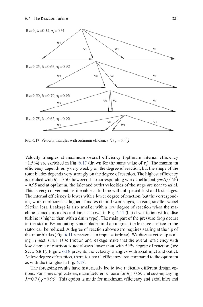
Velocity triangles at maximum overall efficiency (optimum internal efficiency
−1.5 %) are sketched in Fig. 6.17 (drawn for the same value of v s ). The maximum
efficiency depends only very weakly on the degree of reaction, but the shape of the
rotor blades depends very strongly on the degree of reaction. The highest efficiency
is reached with R s = 0.50, however. The corresponding work coefficient y = (h i /2l
2
)
≈ 0.95 and at optimum, the inlet and outlet velocities of the stage are near to axial.
This is very convenient, as it enables a turbine without special first and last stages.
The internal efficiency is lower with a lower degree of reaction, but the corresponding work coefficient is higher. This results in fewer stages, causing smaller wheel
friction loss. Leakage is also smaller with a low degree of reaction when the machine is made as a disc turbine, as shown in Fig. 6.11 (but disc friction with a disc
turbine is higher than with a drum type). The main part of the pressure drop occurs
in the stator. By mounting stator blades in diaphragms, the leakage surface in the
stator can be reduced. A degree of reaction above zero requires sealing at the tip of
the rotor blades (Fig. 6.11 represents an impulse turbine). We discuss rotor tip sealing in Sect. 6.8.1. Disc friction and leakage make that the overall efficiency with
low degree of reaction is not always lower than with 50 % degree of reaction (see
Sect. 6.8.1). Figure 6.18 presents the velocity triangles with axial inlet and outlet.
At low degree of reaction, there is a small efficiency loss compared to the optimum
as with the triangles in Fig. 6.17.
The foregoing results have historically led to two radically different design options. For some applications, manufacturers choose for R s = 0.50 and accompanying
l = 0.7 (y = 0.95). This option is made for maximum efficiency and axial inlet and
Fig. 6.17 Velocity triangles with optimum efficiency 1
(
72 )
°
=
a
6.7 The Reaction Turbine
Velocity triangles at maximum overall efficiency (optimum internal efficiency
−1.5 %) are sketched in Fig. 6.17 (drawn for the same value of v s ). The maximum
efficiency depends only very weakly on the degree of reaction, but the shape of the
rotor blades depends very strongly on the degree of reaction. The highest efficiency
is reached with R s = 0.50, however. The corresponding work coefficient y = (h i /2l
2
)
≈ 0.95 and at optimum, the inlet and outlet velocities of the stage are near to axial.
This is very convenient, as it enables a turbine without special first and last stages.
The internal efficiency is lower with a lower degree of reaction, but the corresponding work coefficient is higher. This results in fewer stages, causing smaller wheel
friction loss. Leakage is also smaller with a low degree of reaction when the machine is made as a disc turbine, as shown in Fig. 6.11 (but disc friction with a disc
turbine is higher than with a drum type). The main part of the pressure drop occurs
in the stator. By mounting stator blades in diaphragms, the leakage surface in the
stator can be reduced. A degree of reaction above zero requires sealing at the tip of
the rotor blades (Fig. 6.11 represents an impulse turbine). We discuss rotor tip sealing in Sect. 6.8.1. Disc friction and leakage make that the overall efficiency with
low degree of reaction is not always lower than with 50 % degree of reaction (see
Sect. 6.8.1). Figure 6.18 presents the velocity triangles with axial inlet and outlet.
At low degree of reaction, there is a small efficiency loss compared to the optimum
as with the triangles in Fig. 6.17.
The foregoing results have historically led to two radically different design options. For some applications, manufacturers choose for R s = 0.50 and accompanying
l = 0.7 (y = 0.95). This option is made for maximum efficiency and axial inlet and
Fig. 6.17 Velocity triangles with optimum efficiency 1
(
72 )
°
=
a