

211
from where:
.
r
r
1
1
f
x
=
+
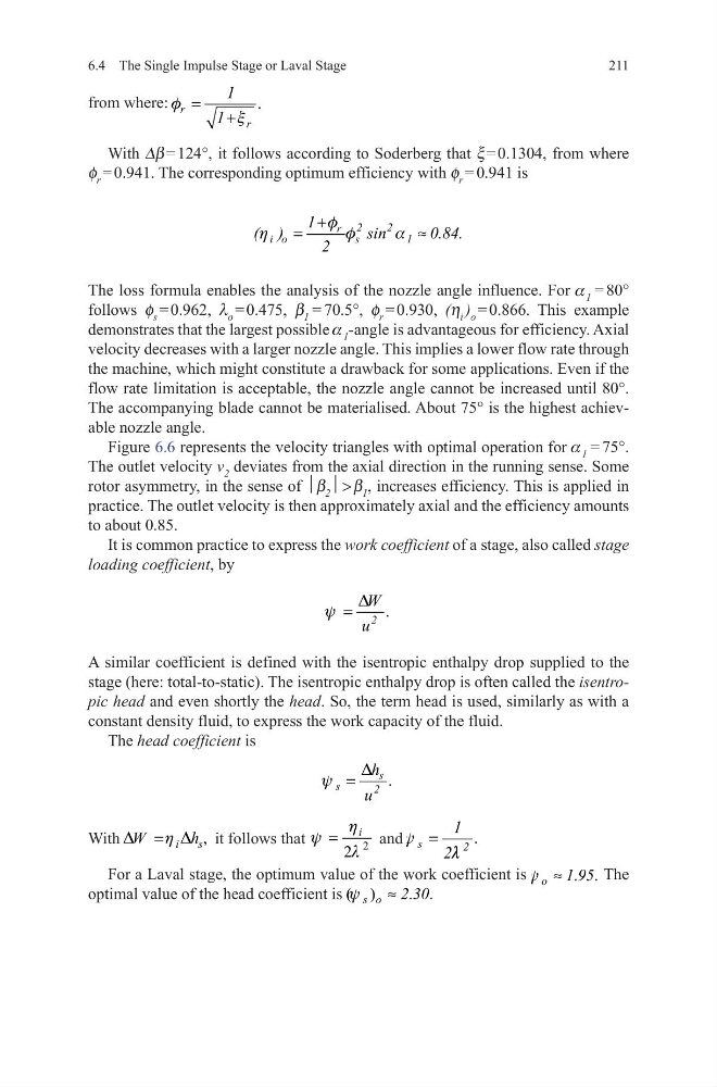
With Dβ = 124°, it follows according to Soderberg that x = 0.1304, from where
f r = 0.941. The corresponding optimum efficiency with f r = 0.941 is
The loss formula enables the analysis of the nozzle angle influence. For a 1 = 80°
follows f s = 0.962, l o = 0.475, β 1 = 70.5°, f r = 0.930, (h i ) o = 0.866. This example
demonstrates that the largest possible a 1 -angle is advantageous for efficiency. Axial
velocity decreases with a larger nozzle angle. This implies a lower flow rate through
the machine, which might constitute a drawback for some applications. Even if the
flow rate limitation is acceptable, the nozzle angle cannot be increased until 80°.
The accompanying blade cannot be materialised. About 75° is the highest achievable nozzle angle.
Figure 6.6 represents the velocity triangles with optimal operation for a 1 = 75°.
The outlet velocity v 2 deviates from the axial direction in the running sense. Some
rotor asymmetry, in the sense of β 2 > β 1 , increases efficiency. This is applied in
practice. The outlet velocity is then approximately axial and the efficiency amounts
to about 0.85.
It is common practice to express the work coefficient of a stage, also called stage
loading coefficient, by
A similar coefficient is defined with the isentropic enthalpy drop supplied to the
stage (here: total-to-static). The isentropic enthalpy drop is often called the isentropic head and even shortly the head. So, the term head is used, similarly as with a
constant density fluid, to express the work capacity of the fluid.
The head coefficient is
With
,
i
s
W
h
D
h D
=
it follows that
2
2
i
h
y
l
=
and
.
s
2
1
2
y
l
=
For a Laval stage, the optimum value of the work coefficient is
. .
o
1 95
y ≈
The
optimal value of the head coefficient is ( )
. .
s o
2 30
y
≈
2
2
r
i o
s
1
1
( )
sin
0.84.
2
+
=
≈
f
h
f
a
.
2
W
u
D
y =
.
s
s
2
h
u
D
y =
6.4 The Single Impulse Stage or Laval Stage
from where:
.
r
r
1
1
f
x
=
+
With Dβ = 124°, it follows according to Soderberg that x = 0.1304, from where
f r = 0.941. The corresponding optimum efficiency with f r = 0.941 is
The loss formula enables the analysis of the nozzle angle influence. For a 1 = 80°
follows f s = 0.962, l o = 0.475, β 1 = 70.5°, f r = 0.930, (h i ) o = 0.866. This example
demonstrates that the largest possible a 1 -angle is advantageous for efficiency. Axial
velocity decreases with a larger nozzle angle. This implies a lower flow rate through
the machine, which might constitute a drawback for some applications. Even if the
flow rate limitation is acceptable, the nozzle angle cannot be increased until 80°.
The accompanying blade cannot be materialised. About 75° is the highest achievable nozzle angle.
Figure 6.6 represents the velocity triangles with optimal operation for a 1 = 75°.
The outlet velocity v 2 deviates from the axial direction in the running sense. Some
rotor asymmetry, in the sense of β 2 > β 1 , increases efficiency. This is applied in
practice. The outlet velocity is then approximately axial and the efficiency amounts
to about 0.85.
It is common practice to express the work coefficient of a stage, also called stage
loading coefficient, by
A similar coefficient is defined with the isentropic enthalpy drop supplied to the
stage (here: total-to-static). The isentropic enthalpy drop is often called the isentropic head and even shortly the head. So, the term head is used, similarly as with a
constant density fluid, to express the work capacity of the fluid.
The head coefficient is
With
,
i
s
W
h
D
h D
=
it follows that
2
2
i
h
y
l
=
and
.
s
2
1
2
y
l
=
For a Laval stage, the optimum value of the work coefficient is
. .
o
1 95
y ≈
The
optimal value of the head coefficient is ( )
. .
s o
2 30
y
≈
2
2
r
i o
s
1
1
( )
sin
0.84.
2
+
=
≈
f
h
f
a
.
2
W
u
D
y =
.
s
s
2
h
u
D
y =
6.4 The Single Impulse Stage or Laval Stage