

186
5 Performance Measurement
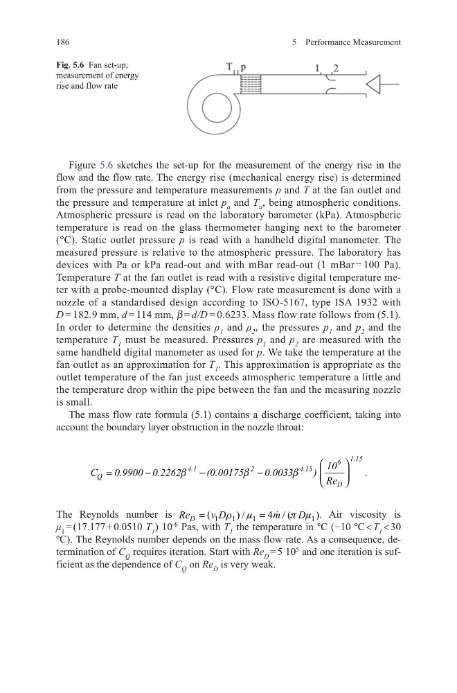
Figure 5.6 sketches the set-up for the measurement of the energy rise in the
flow and the flow rate. The energy rise (mechanical energy rise) is determined
from the pressure and temperature measurements p and T at the fan outlet and
the pressure and temperature at inlet p a and T a , being atmospheric conditions.
Atmospheric pressure is read on the laboratory barometer (kPa). Atmospheric
temperature is read on the glass thermometer hanging next to the barometer
(°C). Static outlet pressure p is read with a handheld digital manometer. The
measured pressure is relative to the atmospheric pressure. The laboratory has
devices with Pa or kPa read-out and with mBar read-out (1 mBar = 100 Pa).
Temperature T at the fan outlet is read with a resistive digital temperature meter with a probe-mounted display (°C). Flow rate measurement is done with a
nozzle of a standardised design according to ISO-5167, type ISA 1932 with
D = 182.9 mm, d = 114 mm, β = d/D = 0.6233. Mass flow rate follows from (5.1).
In order to determine the densities ρ 1 and ρ 2 , the pressures p 1 and p 2 and the
temperature T 1 must be measured. Pressures p 1 and p 2 are measured with the
same handheld digital manometer as used for p. We take the temperature at the
fan outlet as an approximation for T 1 . This approximation is appropriate as the
outlet temperature of the fan just exceeds atmospheric temperature a little and
the temperature drop within the pipe between the fan and the measuring nozzle
is small.
The mass flow rate formula (5.1) contains a discharge coefficient, taking into
account the boundary layer obstruction in the nozzle throat:
The Reynolds number is
1
1
1
1
(
) /
4 / (
)
D
Re
v D
m
D
r m
p m
=
=
. Air viscosity is
μ 1 = (17.177 + 0.0510 T 1 ) 10
-6
Pas, with T 1 the temperature in °C (−10 °C < T 1 < 30
°C). The Reynolds number depends on the mass flow rate. As a consequence, determination of C Q requires iteration. Start with Re D = 5 10
5
and one iteration is sufficient as the dependence of C Q on Re D is very weak.
.
.
1 15
6
4.1
2
4.15
Q
D
10
C
0.9900 0.2262
(0.00175
0.0033
) Re
b
b
b
=
−
−
−
Fig. 5.6 Fan set-up;
measurement of energy
rise and flow rate
5 Performance Measurement
Figure 5.6 sketches the set-up for the measurement of the energy rise in the
flow and the flow rate. The energy rise (mechanical energy rise) is determined
from the pressure and temperature measurements p and T at the fan outlet and
the pressure and temperature at inlet p a and T a , being atmospheric conditions.
Atmospheric pressure is read on the laboratory barometer (kPa). Atmospheric
temperature is read on the glass thermometer hanging next to the barometer
(°C). Static outlet pressure p is read with a handheld digital manometer. The
measured pressure is relative to the atmospheric pressure. The laboratory has
devices with Pa or kPa read-out and with mBar read-out (1 mBar = 100 Pa).
Temperature T at the fan outlet is read with a resistive digital temperature meter with a probe-mounted display (°C). Flow rate measurement is done with a
nozzle of a standardised design according to ISO-5167, type ISA 1932 with
D = 182.9 mm, d = 114 mm, β = d/D = 0.6233. Mass flow rate follows from (5.1).
In order to determine the densities ρ 1 and ρ 2 , the pressures p 1 and p 2 and the
temperature T 1 must be measured. Pressures p 1 and p 2 are measured with the
same handheld digital manometer as used for p. We take the temperature at the
fan outlet as an approximation for T 1 . This approximation is appropriate as the
outlet temperature of the fan just exceeds atmospheric temperature a little and
the temperature drop within the pipe between the fan and the measuring nozzle
is small.
The mass flow rate formula (5.1) contains a discharge coefficient, taking into
account the boundary layer obstruction in the nozzle throat:
The Reynolds number is
1
1
1
1
(
) /
4 / (
)
D
Re
v D
m
D
r m
p m
=
=
. Air viscosity is
μ 1 = (17.177 + 0.0510 T 1 ) 10
-6
Pas, with T 1 the temperature in °C (−10 °C < T 1 < 30
°C). The Reynolds number depends on the mass flow rate. As a consequence, determination of C Q requires iteration. Start with Re D = 5 10
5
and one iteration is sufficient as the dependence of C Q on Re D is very weak.
.
.
1 15
6
4.1
2
4.15
Q
D
10
C
0.9900 0.2262
(0.00175
0.0033
) Re
b
b
b
=
−
−
−
Fig. 5.6 Fan set-up;
measurement of energy
rise and flow rate