

172
4 Compressible Fluids
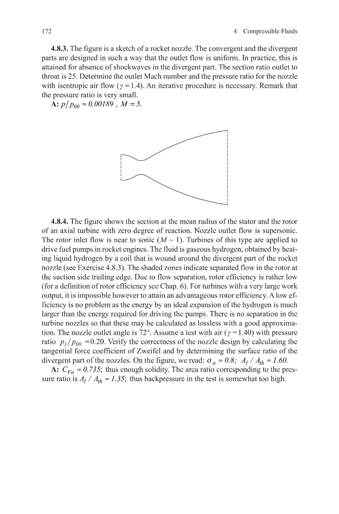
4.8.3. The figure is a sketch of a rocket nozzle. The convergent and the divergent
parts are designed in such a way that the outlet flow is uniform. In practice, this is
attained for absence of shockwaves in the divergent part. The section ratio outlet to
throat is 25. Determine the outlet Mach number and the pressure ratio for the nozzle
with isentropic air flow ( γ = 1.4). An iterative procedure is necessary. Remark that
the pressure ratio is very small.
A:
00
p p
0.00189
≈
, M 5.
=
4.8.4. The figure shows the section at the mean radius of the stator and the rotor
of an axial turbine with zero degree of reaction. Nozzle outlet flow is supersonic.
The rotor inlet flow is near to sonic ( M ~ 1). Turbines of this type are applied to
drive fuel pumps in rocket engines. The fluid is gaseous hydrogen, obtained by heating liquid hydrogen by a coil that is wound around the divergent part of the rocket
nozzle (see Exercise 4.8.3). The shaded zones indicate separated flow in the rotor at
the suction side trailing edge. Due to flow separation, rotor efficiency is rather low
(for a definition of rotor efficiency see Chap. 6). For turbines with a very large work
output, it is impossible however to attain an advantageous rotor efficiency. A low efficiency is no problem as the energy by an ideal expansion of the hydrogen is much
larger than the energy required for driving the pumps. There is no separation in the
turbine nozzles so that these may be calculated as lossless with a good approximation. The nozzle outlet angle is 72°. Assume a test with air ( γ = 1.40) with pressure
ratio p p
1
00 = 0.20. Verify the correctness of the nozzle design by calculating the
tangential force coefficient of Zweifel and by determining the surface ratio of the
divergent part of the nozzles. On the figure, we read: a
1
th
0.8; A / A
1.60.
s ≈
≈
A:
;
Fu
C
0.735
≈
thus enough solidity. The area ratio corresponding to the pressure ratio is
;
1
th
A / A
1.35
≈
thus backpressure in the test is somewhat too high.
4 Compressible Fluids
4.8.3. The figure is a sketch of a rocket nozzle. The convergent and the divergent
parts are designed in such a way that the outlet flow is uniform. In practice, this is
attained for absence of shockwaves in the divergent part. The section ratio outlet to
throat is 25. Determine the outlet Mach number and the pressure ratio for the nozzle
with isentropic air flow ( γ = 1.4). An iterative procedure is necessary. Remark that
the pressure ratio is very small.
A:
00
p p
0.00189
≈
, M 5.
=
4.8.4. The figure shows the section at the mean radius of the stator and the rotor
of an axial turbine with zero degree of reaction. Nozzle outlet flow is supersonic.
The rotor inlet flow is near to sonic ( M ~ 1). Turbines of this type are applied to
drive fuel pumps in rocket engines. The fluid is gaseous hydrogen, obtained by heating liquid hydrogen by a coil that is wound around the divergent part of the rocket
nozzle (see Exercise 4.8.3). The shaded zones indicate separated flow in the rotor at
the suction side trailing edge. Due to flow separation, rotor efficiency is rather low
(for a definition of rotor efficiency see Chap. 6). For turbines with a very large work
output, it is impossible however to attain an advantageous rotor efficiency. A low efficiency is no problem as the energy by an ideal expansion of the hydrogen is much
larger than the energy required for driving the pumps. There is no separation in the
turbine nozzles so that these may be calculated as lossless with a good approximation. The nozzle outlet angle is 72°. Assume a test with air ( γ = 1.40) with pressure
ratio p p
1
00 = 0.20. Verify the correctness of the nozzle design by calculating the
tangential force coefficient of Zweifel and by determining the surface ratio of the
divergent part of the nozzles. On the figure, we read: a
1
th
0.8; A / A
1.60.
s ≈
≈
A:
;
Fu
C
0.735
≈
thus enough solidity. The area ratio corresponding to the pressure ratio is
;
1
th
A / A
1.35
≈
thus backpressure in the test is somewhat too high.