

132
3 Fans
(3.39)
Further
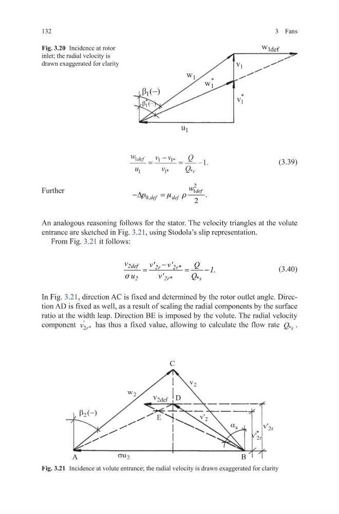
An analogous reasoning follows for the stator. The velocity triangles at the volute
entrance are sketched in Fig. 3.21, using Stodola’s slip representation.
From Fig. 3.21 it follows:
(3.40)
In Fig. 3.21, direction AC is fixed and determined by the rotor outlet angle. Direction AD is fixed as well, as a result of scaling the radial components by the surface
ratio at the width leap. Direction BE is imposed by the volute. The radial velocity
component v r
2 *
'
has thus a fixed value, allowing to calculate the flow rate Q s
* .
w
u
v v
v
Q
Q
def
r
1
1
1
1
1
1
=
−
=
−
*
*
*
.
2
1
0,
.
2
def
def
def
w
p
m r
−∆
=
.
2def
2r
2r*
2
2r*
* s
v
v'
v'
Q 1
u
v'
Q
s
−
=
=
−
Fig. 3.21 Incidence at volute entrance; the radial velocity is drawn exaggerated for clarity
Fig. 3.20 Incidence at rotor
inlet; the radial velocity is
drawn exaggerated for clarity
3 Fans
(3.39)
Further
An analogous reasoning follows for the stator. The velocity triangles at the volute
entrance are sketched in Fig. 3.21, using Stodola’s slip representation.
From Fig. 3.21 it follows:
(3.40)
In Fig. 3.21, direction AC is fixed and determined by the rotor outlet angle. Direction AD is fixed as well, as a result of scaling the radial components by the surface
ratio at the width leap. Direction BE is imposed by the volute. The radial velocity
component v r
2 *
'
has thus a fixed value, allowing to calculate the flow rate Q s
* .
w
u
v v
v
Q
Q
def
r
1
1
1
1
1
1
=
−
=
−
*
*
*
.
2
1
0,
.
2
def
def
def
w
p
m r
−∆
=
.
2def
2r
2r*
2
2r*
* s
v
v'
v'
Q 1
u
v'
Q
s
−
=
=
−
Fig. 3.21 Incidence at volute entrance; the radial velocity is drawn exaggerated for clarity
Fig. 3.20 Incidence at rotor
inlet; the radial velocity is
drawn exaggerated for clarity