

3.4 Internal Losses with Radial Fans
131
consequence is that the blade angle corresponding to the optimum diameter does
not depend on the velocity factor. The minimum of w 1 is obtained for tg
b
β 1
2
= − ,
thus β 1
55
b
≈ −
°
. This is, in principle, a universal result. The corresponding inlet
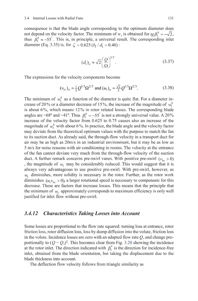
diameter (Eq. 3.35) is, for ζ =
=
0 625
0 40
1
1
.
( /
. )
b d
:
(3.37)
The expressions for the velocity components become
(3.38)
The minimum of w
b
1 as a function of the diameter is quite flat. For a diameter increase of 20 % or a diameter decrease of 15 %, the increase of the magnitude of w
b
1
is about 6 %, which means 12 % in rotor related losses. The corresponding blade
angles are −68º and −41º. Thus β 1
55
b
= −
°
is not a strongly universal value. A 20 %
increase of the velocity factor from 0.625 to 0.75 causes also an increase of the
magnitude of w
b
1 with about 6 %. In practice, the blade angle and the velocity factor
may deviate from the theoretical optimum values with the purpose to match the fan
to its suction duct. As already said, the through-flow velocity in a transport duct for
air may be as high as 20m/s in an industrial environment, but it may be as low as
5 m/s for noise reasons with air conditioning in rooms. The velocity at the entrance
of the fan cannot deviate very much from the through-flow velocity of the suction
duct. A further remark concerns pre-swirl vanes. With positive pre-swirl (
)
v u
1
0
>
, the magnitude of w 1 may be considerably reduced. This would suggest that it is
always very advantageous to use positive pre-swirl. With pre-swirl, however, as
w 1 diminishes, more solidity is necessary in the rotor. Further, as the rotor work
diminishes (
)
u v u
1 1
0
> , a larger rotational speed is necessary to compensate for this
decrease. These are factors that increase losses. This means that the principle that
the minimum of w 1 approximately corresponds to maximum efficiency is only well
justified for inlet flow without pre-swirl.
3.4.12 Characteristics Taking Losses into Account
Some losses are proportional to the flow rate squared: turning loss at entrance, rotor
friction loss, rotor diffusion loss, loss by dump diffusion into the volute, friction loss
in the volute. Incidence losses are zero with an adapted flow rate Q * and change proportionally to ( Q − Q * )
2
. This becomes clear from Fig. 3.20 showing the incidence
at the rotor inlet. The direction indicated with β 1
*
is the direction for incidence-free
inlet, obtained from the blade orientation, but taking the displacement due to the
blade thickness into account.
The deflection flow velocity follows from triangle similarity as
( )
.
/
d
Q
o
1
1 3
2
≈
Ω
1/3 2/3
1/3 2/3
2
1
1
1
2
2
( )
and ( )
.
r o
o
v
Q
u
Q
≈
Ω
≈
Ω
131
consequence is that the blade angle corresponding to the optimum diameter does
not depend on the velocity factor. The minimum of w 1 is obtained for tg
b
β 1
2
= − ,
thus β 1
55
b
≈ −
°
. This is, in principle, a universal result. The corresponding inlet
diameter (Eq. 3.35) is, for ζ =
=
0 625
0 40
1
1
.
( /
. )
b d
:
(3.37)
The expressions for the velocity components become
(3.38)
The minimum of w
b
1 as a function of the diameter is quite flat. For a diameter increase of 20 % or a diameter decrease of 15 %, the increase of the magnitude of w
b
1
is about 6 %, which means 12 % in rotor related losses. The corresponding blade
angles are −68º and −41º. Thus β 1
55
b
= −
°
is not a strongly universal value. A 20 %
increase of the velocity factor from 0.625 to 0.75 causes also an increase of the
magnitude of w
b
1 with about 6 %. In practice, the blade angle and the velocity factor
may deviate from the theoretical optimum values with the purpose to match the fan
to its suction duct. As already said, the through-flow velocity in a transport duct for
air may be as high as 20m/s in an industrial environment, but it may be as low as
5 m/s for noise reasons with air conditioning in rooms. The velocity at the entrance
of the fan cannot deviate very much from the through-flow velocity of the suction
duct. A further remark concerns pre-swirl vanes. With positive pre-swirl (
)
v u
1
0
>
, the magnitude of w 1 may be considerably reduced. This would suggest that it is
always very advantageous to use positive pre-swirl. With pre-swirl, however, as
w 1 diminishes, more solidity is necessary in the rotor. Further, as the rotor work
diminishes (
)
u v u
1 1
0
> , a larger rotational speed is necessary to compensate for this
decrease. These are factors that increase losses. This means that the principle that
the minimum of w 1 approximately corresponds to maximum efficiency is only well
justified for inlet flow without pre-swirl.
3.4.12 Characteristics Taking Losses into Account
Some losses are proportional to the flow rate squared: turning loss at entrance, rotor
friction loss, rotor diffusion loss, loss by dump diffusion into the volute, friction loss
in the volute. Incidence losses are zero with an adapted flow rate Q * and change proportionally to ( Q − Q * )
2
. This becomes clear from Fig. 3.20 showing the incidence
at the rotor inlet. The direction indicated with β 1
*
is the direction for incidence-free
inlet, obtained from the blade orientation, but taking the displacement due to the
blade thickness into account.
The deflection flow velocity follows from triangle similarity as
( )
.
/
d
Q
o
1
1 3
2
≈
Ω
1/3 2/3
1/3 2/3
2
1
1
1
2
2
( )
and ( )
.
r o
o
v
Q
u
Q
≈
Ω
≈
Ω