

128
3 Fans
Centrifugal fans with forward curved blades (Fig. 3.14, fourth blade form) have
recirculation flow in the rotor, also for the design flow rate. These machines have
a very low degree of reaction. Therefore, they can be built with a diameter ratio d 1 /d 2 close to 1 (0.85–0.9 are typical) as pressure increase by the centrifugal
term, (
/ 2
)
2
2
2
1
u u
−
, does not have to be high. With a high value of the inlet diameter, the flow rate can be maximised for a given rotor diameter. Since the work
coefficient is also high, centrifugal fans with forward curved blades are the most
compact ones for a given duty of flow rate and total pressure rise. For this reason,
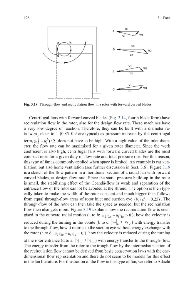
this type of fan is commonly applied when space is limited. An example is car ventilation, but also home ventilation (see further discussion in Sect. 3.6). Figure 3.19
is a sketch of the flow pattern in a meridional section of a radial fan with forward
curved blades, at design flow rate. Since the static pressure build-up in the rotor
is small, the stabilising effect of the Coandă-flow is weak and separation of the
entrance flow of the rotor cannot be avoided at the shroud. The option is then typically taken to make the width of the rotor constant and much bigger than follows
from equal through-flow areas of rotor inlet and suction eye ( /
. )
b d
1
1
0 25
=
. The
through-flow of the rotor can then take the space as needed, but the recirculation
flow then also gets room. Figure 3.19 explains how the recirculation flow is energised in the outward radial motion (a to b: u v
u v
u
u
2 2
1 1
0
−
> ), how the velocity is
reduced during the turning in the volute (b to c: v
v
b
c
2
2
>
) with energy transfer
to the through-flow, how it returns to the suction eye without energy exchange with
the rotor (c to d: u v
u v
u
u
2 2
1 1
0
−
= ), how the velocity is reduced during the turning
at the rotor entrance (d to a: v
v
d
a
1
1
>
) with energy transfer to the through-flow.
The energy transfer from the rotor to the trough-flow by the intermediate action of
the recirculation flow cannot be derived from basic conservation laws with the onedimensional flow representation and there do not seem to be models for this effect
in the fan literature. For illustration of the flow in this type of fan, we refer to Adachi
Fig. 3.19 Through-flow and recirculation flow in a rotor with forward curved blades
3 Fans
Centrifugal fans with forward curved blades (Fig. 3.14, fourth blade form) have
recirculation flow in the rotor, also for the design flow rate. These machines have
a very low degree of reaction. Therefore, they can be built with a diameter ratio d 1 /d 2 close to 1 (0.85–0.9 are typical) as pressure increase by the centrifugal
term, (
/ 2
)
2
2
2
1
u u
−
, does not have to be high. With a high value of the inlet diameter, the flow rate can be maximised for a given rotor diameter. Since the work
coefficient is also high, centrifugal fans with forward curved blades are the most
compact ones for a given duty of flow rate and total pressure rise. For this reason,
this type of fan is commonly applied when space is limited. An example is car ventilation, but also home ventilation (see further discussion in Sect. 3.6). Figure 3.19
is a sketch of the flow pattern in a meridional section of a radial fan with forward
curved blades, at design flow rate. Since the static pressure build-up in the rotor
is small, the stabilising effect of the Coandă-flow is weak and separation of the
entrance flow of the rotor cannot be avoided at the shroud. The option is then typically taken to make the width of the rotor constant and much bigger than follows
from equal through-flow areas of rotor inlet and suction eye ( /
. )
b d
1
1
0 25
=
. The
through-flow of the rotor can then take the space as needed, but the recirculation
flow then also gets room. Figure 3.19 explains how the recirculation flow is energised in the outward radial motion (a to b: u v
u v
u
u
2 2
1 1
0
−
> ), how the velocity is
reduced during the turning in the volute (b to c: v
v
b
c
2
2
>
) with energy transfer
to the through-flow, how it returns to the suction eye without energy exchange with
the rotor (c to d: u v
u v
u
u
2 2
1 1
0
−
= ), how the velocity is reduced during the turning
at the rotor entrance (d to a: v
v
d
a
1
1
>
) with energy transfer to the through-flow.
The energy transfer from the rotor to the trough-flow by the intermediate action of
the recirculation flow cannot be derived from basic conservation laws with the onedimensional flow representation and there do not seem to be models for this effect
in the fan literature. For illustration of the flow in this type of fan, we refer to Adachi
Fig. 3.19 Through-flow and recirculation flow in a rotor with forward curved blades