

3.4 Internal Losses with Radial Fans
127
balance between pipe cost and energy dissipation). In house ventilating systems,
the velocity typically has to be limited to about 5 m/s because of noise generation
limitation. On the suction side of a fan, velocities may be up to 30 m/s, certainly for
a fan taking air directly from a large space. The meridional component of the velocity at the rotor inlet may be much lower. With β 1 ≈ − 60° is v 1m ≈ 0.6 u 1 . This implies
that the order of magnitude of v 1m may be around 12 m/s at lower u 1 values. This
requires then velocity reduction between the suction eye and the rotor inlet (inlet
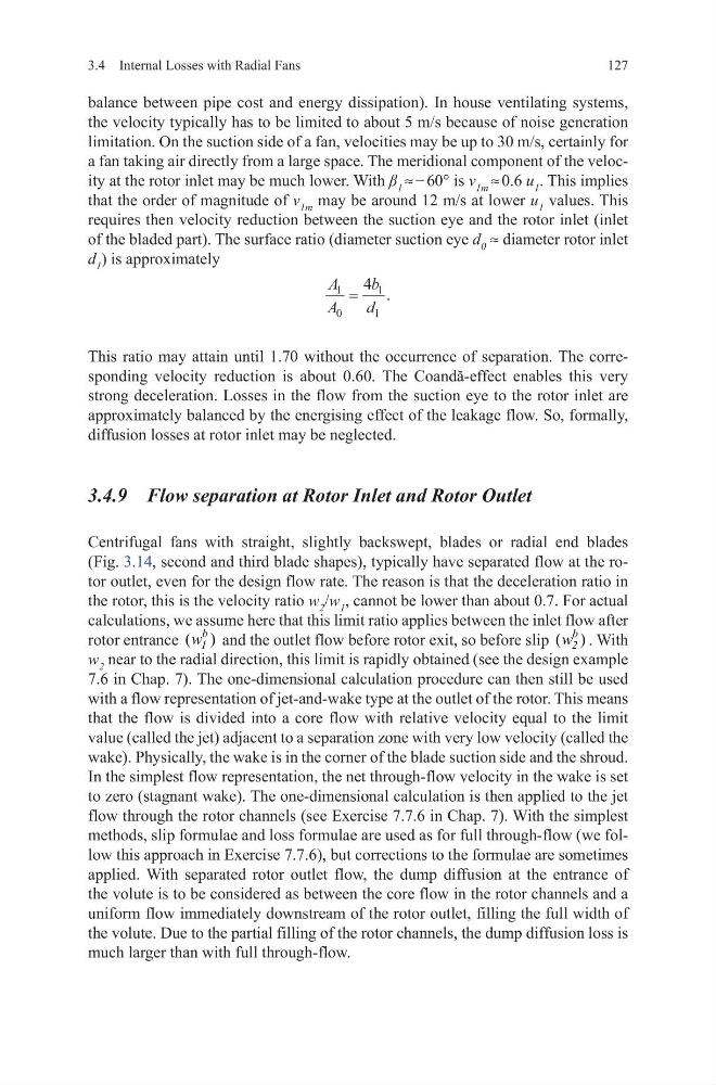
of the bladed part). The surface ratio (diameter suction eye d 0 ≈ diameter rotor inlet
d 1 ) is approximately
This ratio may attain until 1.70 without the occurrence of separation. The corresponding velocity reduction is about 0.60. The Coandă-effect enables this very
strong deceleration. Losses in the flow from the suction eye to the rotor inlet are
approximately balanced by the energising effect of the leakage flow. So, formally,
diffusion losses at rotor inlet may be neglected.
3.4.9 Flow separation at Rotor Inlet and Rotor Outlet
Centrifugal fans with straight, slightly backswept, blades or radial end blades
(Fig. 3.14, second and third blade shapes), typically have separated flow at the rotor outlet, even for the design flow rate. The reason is that the deceleration ratio in
the rotor, this is the velocity ratio w 2 /w 1 , cannot be lower than about 0.7. For actual
calculations, we assume here that this limit ratio applies between the inlet flow after
rotor entrance ( )
b
1
w and the outlet flow before rotor exit, so before slip ( )
b
2
w . With
w 2 near to the radial direction, this limit is rapidly obtained (see the design example
7.6 in Chap. 7). The one-dimensional calculation procedure can then still be used
with a flow representation of jet-and-wake type at the outlet of the rotor. This means
that the flow is divided into a core flow with relative velocity equal to the limit
value (called the jet) adjacent to a separation zone with very low velocity (called the
wake). Physically, the wake is in the corner of the blade suction side and the shroud.
In the simplest flow representation, the net through-flow velocity in the wake is set
to zero (stagnant wake). The one-dimensional calculation is then applied to the jet
flow through the rotor channels (see Exercise 7.7.6 in Chap. 7). With the simplest
methods, slip formulae and loss formulae are used as for full through-flow (we follow this approach in Exercise 7.7.6), but corrections to the formulae are sometimes
applied. With separated rotor outlet flow, the dump diffusion at the entrance of
the volute is to be considered as between the core flow in the rotor channels and a
uniform flow immediately downstream of the rotor outlet, filling the full width of
the volute. Due to the partial filling of the rotor channels, the dump diffusion loss is
much larger than with full through-flow.
A
A
b
d
1
0
1
1
4
=
.
127
balance between pipe cost and energy dissipation). In house ventilating systems,
the velocity typically has to be limited to about 5 m/s because of noise generation
limitation. On the suction side of a fan, velocities may be up to 30 m/s, certainly for
a fan taking air directly from a large space. The meridional component of the velocity at the rotor inlet may be much lower. With β 1 ≈ − 60° is v 1m ≈ 0.6 u 1 . This implies
that the order of magnitude of v 1m may be around 12 m/s at lower u 1 values. This
requires then velocity reduction between the suction eye and the rotor inlet (inlet
of the bladed part). The surface ratio (diameter suction eye d 0 ≈ diameter rotor inlet
d 1 ) is approximately
This ratio may attain until 1.70 without the occurrence of separation. The corresponding velocity reduction is about 0.60. The Coandă-effect enables this very
strong deceleration. Losses in the flow from the suction eye to the rotor inlet are
approximately balanced by the energising effect of the leakage flow. So, formally,
diffusion losses at rotor inlet may be neglected.
3.4.9 Flow separation at Rotor Inlet and Rotor Outlet
Centrifugal fans with straight, slightly backswept, blades or radial end blades
(Fig. 3.14, second and third blade shapes), typically have separated flow at the rotor outlet, even for the design flow rate. The reason is that the deceleration ratio in
the rotor, this is the velocity ratio w 2 /w 1 , cannot be lower than about 0.7. For actual
calculations, we assume here that this limit ratio applies between the inlet flow after
rotor entrance ( )
b
1
w and the outlet flow before rotor exit, so before slip ( )
b
2
w . With
w 2 near to the radial direction, this limit is rapidly obtained (see the design example
7.6 in Chap. 7). The one-dimensional calculation procedure can then still be used
with a flow representation of jet-and-wake type at the outlet of the rotor. This means
that the flow is divided into a core flow with relative velocity equal to the limit
value (called the jet) adjacent to a separation zone with very low velocity (called the
wake). Physically, the wake is in the corner of the blade suction side and the shroud.
In the simplest flow representation, the net through-flow velocity in the wake is set
to zero (stagnant wake). The one-dimensional calculation is then applied to the jet
flow through the rotor channels (see Exercise 7.7.6 in Chap. 7). With the simplest
methods, slip formulae and loss formulae are used as for full through-flow (we follow this approach in Exercise 7.7.6), but corrections to the formulae are sometimes
applied. With separated rotor outlet flow, the dump diffusion at the entrance of
the volute is to be considered as between the core flow in the rotor channels and a
uniform flow immediately downstream of the rotor outlet, filling the full width of
the volute. Due to the partial filling of the rotor channels, the dump diffusion loss is
much larger than with full through-flow.
A
A
b
d
1
0
1
1
4
=
.