

95
2.5 Exercises
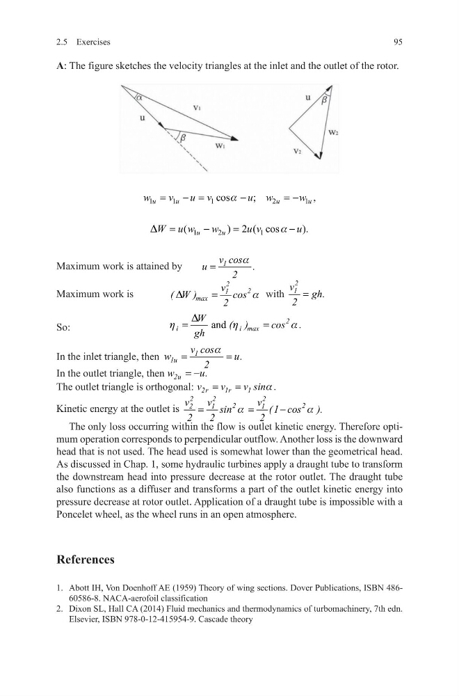
A: The figure sketches the velocity triangles at the inlet and the outlet of the rotor.
Maximum work is attained by
1
v cos
u
.
2
a
=
Maximum work is
2
2
1
max
v
( W )
cos
2
D
a
=
with
2
1
v
gh.
2
=
So:
and
2
i
i max
W
( )
cos .
gh
D
h
h
a
=
=
In the inlet triangle, then
1
1u
v cos
w
u.
2
a
=
=
In the outlet triangle, then 2u
w
u.
= −
The outlet triangle is orthogonal: 2r
1 r
1
v
v
v sin .
a
=
=
Kinetic energy at the outlet is
2
2
2
2
2
2
1
1
v
v
v
sin
( 1 cos ).
2
2
2
a
a
=
=
−
The only loss occurring within the flow is outlet kinetic energy. Therefore optimum operation corresponds to perpendicular outflow. Another loss is the downward
head that is not used. The head used is somewhat lower than the geometrical head.
As discussed in Chap. 1, some hydraulic turbines apply a draught tube to transform
the downstream head into pressure decrease at the rotor outlet. The draught tube
also functions as a diffuser and transforms a part of the outlet kinetic energy into
pressure decrease at rotor outlet. Application of a draught tube is impossible with a
Poncelet wheel, as the wheel runs in an open atmosphere.
References
1. Abott IH, Von Doenhoff AE (1959) Theory of wing sections. Dover Publications, ISBN 48660586-8. NACA-aerofoil classification
2. Dixon SL, Hall CA (2014) Fluid mechanics and thermodynamics of turbomachinery, 7th edn.
Elsevier, ISBN 978-0-12-415954-9. Cascade theory
1
1
1
2
1
cos
;
,
u
u
u
u
w
v
u v
u w
w
a
=
− =
−
= −
1
2
1
(
) 2 ( cos
).
u
u
W u w
w
u v
u
D
a
=
−
=
−
2.5 Exercises
A: The figure sketches the velocity triangles at the inlet and the outlet of the rotor.
Maximum work is attained by
1
v cos
u
.
2
a
=
Maximum work is
2
2
1
max
v
( W )
cos
2
D
a
=
with
2
1
v
gh.
2
=
So:
and
2
i
i max
W
( )
cos .
gh
D
h
h
a
=
=
In the inlet triangle, then
1
1u
v cos
w
u.
2
a
=
=
In the outlet triangle, then 2u
w
u.
= −
The outlet triangle is orthogonal: 2r
1 r
1
v
v
v sin .
a
=
=
Kinetic energy at the outlet is
2
2
2
2
2
2
1
1
v
v
v
sin
( 1 cos ).
2
2
2
a
a
=
=
−
The only loss occurring within the flow is outlet kinetic energy. Therefore optimum operation corresponds to perpendicular outflow. Another loss is the downward
head that is not used. The head used is somewhat lower than the geometrical head.
As discussed in Chap. 1, some hydraulic turbines apply a draught tube to transform
the downstream head into pressure decrease at the rotor outlet. The draught tube
also functions as a diffuser and transforms a part of the outlet kinetic energy into
pressure decrease at rotor outlet. Application of a draught tube is impossible with a
Poncelet wheel, as the wheel runs in an open atmosphere.
References
1. Abott IH, Von Doenhoff AE (1959) Theory of wing sections. Dover Publications, ISBN 48660586-8. NACA-aerofoil classification
2. Dixon SL, Hall CA (2014) Fluid mechanics and thermodynamics of turbomachinery, 7th edn.
Elsevier, ISBN 978-0-12-415954-9. Cascade theory
1
1
1
2
1
cos
;
,
u
u
u
u
w
v
u v
u w
w
a
=
− =
−
= −
1
2
1
(
) 2 ( cos
).
u
u
W u w
w
u v
u
D
a
=
−
=
−