

94
2 Basic Components
diffuser for this application with the Fig. 2.29 diagram. What is the realisable pressure recovery?
A: The most advantageous solution is a conical diffuser with an optimum opening angle (area ratio equal to 2), followed by a sudden expansion. The loss coefficient of the conical diffuser, ,
p id
p
C
C
− , is about 0.135 according to Fig. 2.29. The
loss coefficient of the sudden expansion is 0.25 according to Eq. 2.31 (in reality
somewhat higher due to inflow irregularity). The resulting loss coefficient based
on inlet kinetic energy is 0.135 + 0.25/4 = 0.2025. C p id
, = 0.9375. C p = 0.735. This
solution is more elegant than with guiding surfaces according to Fig. 2.25, which
would require a very small opening angle of the partial diffusers (L/R about 16 according to Fig. 2.29). The pressure recovery of a conical diffuser with area ratio 4 is
as low as for a sudden expansion: C p = 0.375.
2.5.11. A diffuser with a free outlet has L/R 1 = 2 and AR = 1.5. Determine, with
Figs. 2.27 and 2.28, the increase of the pressure recovery coefficient when the inlet
profile is transformed from fully developed into uniform.
A: C p goes from 0.45 to 0.50.
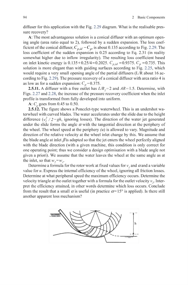
2.5.12. The figure shows a Poncelet-type waterwheel. This is an undershot waterwheel with curved blades. The water accelerates under the slide due to the height
difference (v 1
2
2
/ = gh, ignoring losses). The direction of the water jet generated
under the slide forms the angle a with the tangential direction at the periphery of
the wheel. The wheel speed at the periphery (u) is allowed to vary. Magnitude and
direction of the relative velocity at the wheel inlet change by this. We assume that
the blade angle at inlet β is adapted so that the jet enters the wheel perfectly aligned
with the blade direction (with a given machine, this condition is only correct for
one operating point; thus we consider a design optimisation with a blade angle not
given a priori). We assume that the water leaves the wheel at the same angle as at
the inlet, so that w 2 = w 1 .
Determine a formula for the rotor work at fixed values for v 1 and a and a variable
value for u. Express the internal efficiency of the wheel, ignoring all friction losses.
Determine at what peripheral speed the maximum efficiency occurs. Determine the
velocity triangle at the outlet together with a formula for the outlet velocity v 2 . Interpret the efficiency attained, in other words determine which loss occurs. Conclude
from the result that a small a is useful (in practice a = 15° is applied). Is there still
another apparent loss mechanism?
2 Basic Components
diffuser for this application with the Fig. 2.29 diagram. What is the realisable pressure recovery?
A: The most advantageous solution is a conical diffuser with an optimum opening angle (area ratio equal to 2), followed by a sudden expansion. The loss coefficient of the conical diffuser, ,
p id
p
C
C
− , is about 0.135 according to Fig. 2.29. The
loss coefficient of the sudden expansion is 0.25 according to Eq. 2.31 (in reality
somewhat higher due to inflow irregularity). The resulting loss coefficient based
on inlet kinetic energy is 0.135 + 0.25/4 = 0.2025. C p id
, = 0.9375. C p = 0.735. This
solution is more elegant than with guiding surfaces according to Fig. 2.25, which
would require a very small opening angle of the partial diffusers (L/R about 16 according to Fig. 2.29). The pressure recovery of a conical diffuser with area ratio 4 is
as low as for a sudden expansion: C p = 0.375.
2.5.11. A diffuser with a free outlet has L/R 1 = 2 and AR = 1.5. Determine, with
Figs. 2.27 and 2.28, the increase of the pressure recovery coefficient when the inlet
profile is transformed from fully developed into uniform.
A: C p goes from 0.45 to 0.50.
2.5.12. The figure shows a Poncelet-type waterwheel. This is an undershot waterwheel with curved blades. The water accelerates under the slide due to the height
difference (v 1
2
2
/ = gh, ignoring losses). The direction of the water jet generated
under the slide forms the angle a with the tangential direction at the periphery of
the wheel. The wheel speed at the periphery (u) is allowed to vary. Magnitude and
direction of the relative velocity at the wheel inlet change by this. We assume that
the blade angle at inlet β is adapted so that the jet enters the wheel perfectly aligned
with the blade direction (with a given machine, this condition is only correct for
one operating point; thus we consider a design optimisation with a blade angle not
given a priori). We assume that the water leaves the wheel at the same angle as at
the inlet, so that w 2 = w 1 .
Determine a formula for the rotor work at fixed values for v 1 and a and a variable
value for u. Express the internal efficiency of the wheel, ignoring all friction losses.
Determine at what peripheral speed the maximum efficiency occurs. Determine the
velocity triangle at the outlet together with a formula for the outlet velocity v 2 . Interpret the efficiency attained, in other words determine which loss occurs. Conclude
from the result that a small a is useful (in practice a = 15° is applied). Is there still
another apparent loss mechanism?