

91
2.5 Exercises
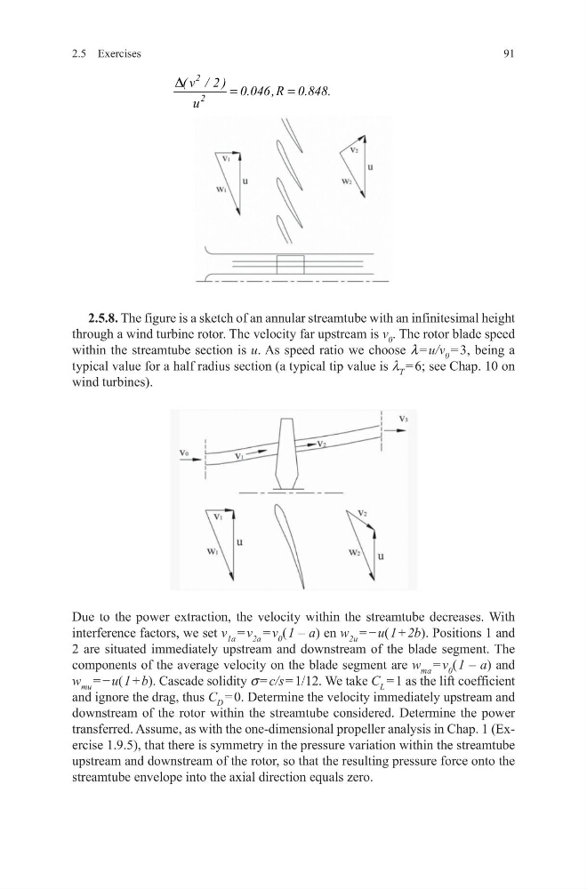
2.5.8. The figure is a sketch of an annular streamtube with an infinitesimal height
through a wind turbine rotor. The velocity far upstream is v 0 . The rotor blade speed
within the streamtube section is u. As speed ratio we choose l = u/v 0 = 3, being a
typical value for a half radius section (a typical tip value is l T = 6; see Chap. 10 on
wind turbines).
Due to the power extraction, the velocity within the streamtube decreases. With
interference factors, we set v 1a = v 2a = v 0 ( 1 – a) en w 2u = − u( 1 + 2b). Positions 1 and
2 are situated immediately upstream and downstream of the blade segment. The
components of the average velocity on the blade segment are w ma = v 0 ( 1 – a) and
w mu = − u( 1 + b). Cascade solidity s = c/s = 1/12. We take C L = 1 as the lift coefficient
and ignore the drag, thus C D = 0. Determine the velocity immediately upstream and
downstream of the rotor within the streamtube considered. Determine the power
transferred. Assume, as with the one-dimensional propeller analysis in Chap. 1 (Exercise 1.9.5), that there is symmetry in the pressure variation within the streamtube
upstream and downstream of the rotor, so that the resulting pressure force onto the
streamtube envelope into the axial direction equals zero.
2
2
( v / 2 ) 0.046 ,R 0.848.
u
D
=
=
2.5 Exercises
2.5.8. The figure is a sketch of an annular streamtube with an infinitesimal height
through a wind turbine rotor. The velocity far upstream is v 0 . The rotor blade speed
within the streamtube section is u. As speed ratio we choose l = u/v 0 = 3, being a
typical value for a half radius section (a typical tip value is l T = 6; see Chap. 10 on
wind turbines).
Due to the power extraction, the velocity within the streamtube decreases. With
interference factors, we set v 1a = v 2a = v 0 ( 1 – a) en w 2u = − u( 1 + 2b). Positions 1 and
2 are situated immediately upstream and downstream of the blade segment. The
components of the average velocity on the blade segment are w ma = v 0 ( 1 – a) and
w mu = − u( 1 + b). Cascade solidity s = c/s = 1/12. We take C L = 1 as the lift coefficient
and ignore the drag, thus C D = 0. Determine the velocity immediately upstream and
downstream of the rotor within the streamtube considered. Determine the power
transferred. Assume, as with the one-dimensional propeller analysis in Chap. 1 (Exercise 1.9.5), that there is symmetry in the pressure variation within the streamtube
upstream and downstream of the rotor, so that the resulting pressure force onto the
streamtube envelope into the axial direction equals zero.
2
2
( v / 2 ) 0.046 ,R 0.848.
u
D
=
=