

90
2 Basic Components
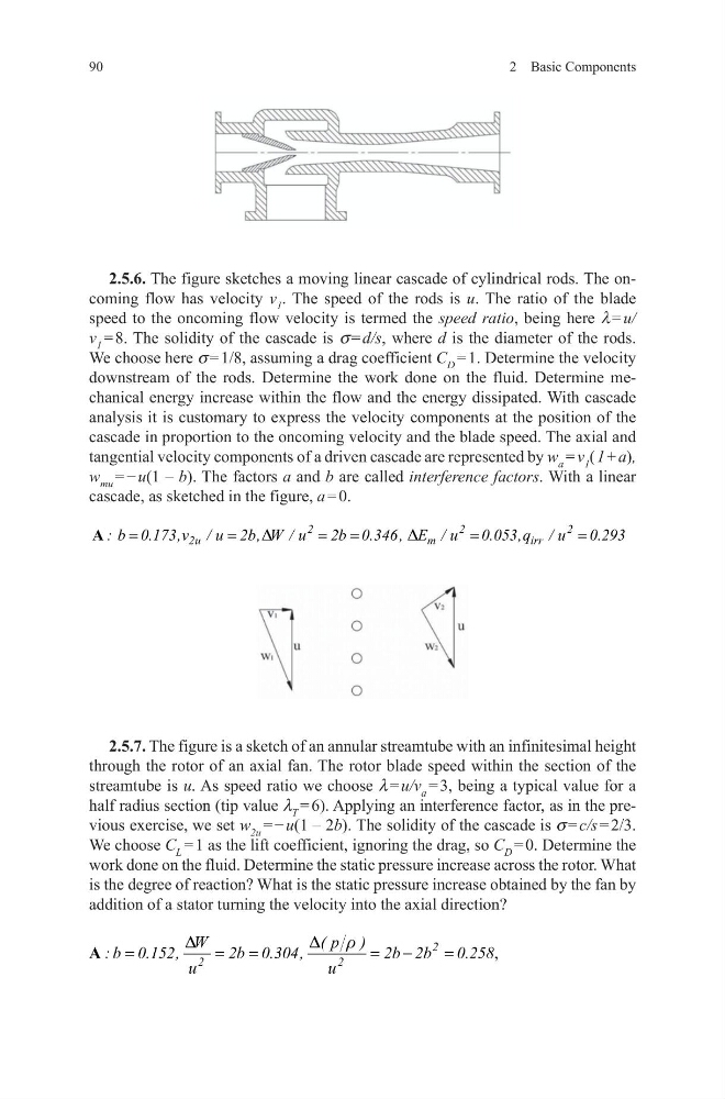
2.5.6. The figure sketches a moving linear cascade of cylindrical rods. The oncoming flow has velocity v 1 . The speed of the rods is u. The ratio of the blade
speed to the oncoming flow velocity is termed the speed ratio, being here l = u/
v 1 = 8. The solidity of the cascade is s = d/s, where d is the diameter of the rods.
We choose here s = 1/8, assuming a drag coefficient C D = 1. Determine the velocity
downstream of the rods. Determine the work done on the fluid. Determine mechanical energy increase within the flow and the energy dissipated. With cascade
analysis it is customary to express the velocity components at the position of the
cascade in proportion to the oncoming velocity and the blade speed. The axial and
tangential velocity components of a driven cascade are represented by w a = v 1 ( 1 + a),
w mu = − u(1 – b). The factors a and b are called interference factors. With a linear
cascade, as sketched in the figure, a = 0.
2.5.7. The figure is a sketch of an annular streamtube with an infinitesimal height
through the rotor of an axial fan. The rotor blade speed within the section of the
streamtube is u. As speed ratio we choose l = u/v a = 3, being a typical value for a
half radius section (tip value l T = 6). Applying an interference factor, as in the previous exercise, we set w 2u = − u(1 – 2b). The solidity of the cascade is s = c/s = 2/3.
We choose C L = 1 as the lift coefficient, ignoring the drag, so C D = 0. Determine the
work done on the fluid. Determine the static pressure increase across the rotor. What
is the degree of reaction? What is the static pressure increase obtained by the fan by
addition of a stator turning the velocity into the axial direction?
2
2
m
irr
2
2u
: b 0.173,v / u 2b, W / u
2b 0.3
E / u 0.053
4
,q /
6,
u 0.293
D
D
=
=
=
= =
=
A
,
2
2
2
W
( p )
: b 0.152,
2b 0.304,
2b 2b
0.258
u
u
D
D
r
=
=
=
= −
=
A
2 Basic Components
2.5.6. The figure sketches a moving linear cascade of cylindrical rods. The oncoming flow has velocity v 1 . The speed of the rods is u. The ratio of the blade
speed to the oncoming flow velocity is termed the speed ratio, being here l = u/
v 1 = 8. The solidity of the cascade is s = d/s, where d is the diameter of the rods.
We choose here s = 1/8, assuming a drag coefficient C D = 1. Determine the velocity
downstream of the rods. Determine the work done on the fluid. Determine mechanical energy increase within the flow and the energy dissipated. With cascade
analysis it is customary to express the velocity components at the position of the
cascade in proportion to the oncoming velocity and the blade speed. The axial and
tangential velocity components of a driven cascade are represented by w a = v 1 ( 1 + a),
w mu = − u(1 – b). The factors a and b are called interference factors. With a linear
cascade, as sketched in the figure, a = 0.
2.5.7. The figure is a sketch of an annular streamtube with an infinitesimal height
through the rotor of an axial fan. The rotor blade speed within the section of the
streamtube is u. As speed ratio we choose l = u/v a = 3, being a typical value for a
half radius section (tip value l T = 6). Applying an interference factor, as in the previous exercise, we set w 2u = − u(1 – 2b). The solidity of the cascade is s = c/s = 2/3.
We choose C L = 1 as the lift coefficient, ignoring the drag, so C D = 0. Determine the
work done on the fluid. Determine the static pressure increase across the rotor. What
is the degree of reaction? What is the static pressure increase obtained by the fan by
addition of a stator turning the velocity into the axial direction?
2
2
m
irr
2
2u
: b 0.173,v / u 2b, W / u
2b 0.3
E / u 0.053
4
,q /
6,
u 0.293
D
D
=
=
=
= =
=
A
,
2
2
2
W
( p )
: b 0.152,
2b 0.304,
2b 2b
0.258
u
u
D
D
r
=
=
=
= −
=
A