

75
2.3 Channels
A criterion for avoidance of separation is that this factor should be limited to 0.5.
This means that ( w max − w 2 ) must not exceed w 2 . This criterion may also be applied
to estimate the lift capacity of a cascade. We will use the local diffusion factor for
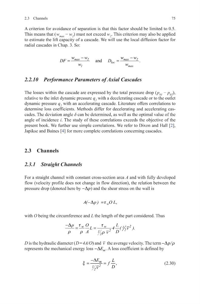
radial cascades in Chap. 3. So:
2.2.10 Performance Parameters of Axial Cascades
The losses within the cascade are expressed by the total pressure drop ( p 01 − p 02 ),
relative to the inlet dynamic pressure q 1 with a decelerating cascade or to the outlet
dynamic pressure q 2 with an accelerating cascade. Literature offers correlations to
determine loss coefficients. Methods differ for decelerating and accelerating cascades. The deviation angle δ can be determined, as well as the optimal value of the
angle of incidence i. The study of these correlations exceeds the objective of the
present book. We further use simple correlations. We refer to Dixon and Hall [2],
Japikse and Baines [4] for more complete correlations concerning cascades.
2.3 Channels
2.3.1 Straight Channels
For a straight channel with constant cross-section area A and with fully developed
flow (velocity profile does not change in flow direction), the relation between the
pressure drop (denoted here by
p
D
− ) and the shear stress on the wall is
with O being the circumference and L the length of the part considered. Thus
D is the hydraulic diameter ( D = 4A/O) and v the average velocity. The term
p/
D r
−
represents the mechanical energy loss
m
E
D
−
. A loss coefficient is defined by
(2.30)
and
max
2
max
2
loc
1
max
w
w
w
w
DF
D
.
w
w
−
−
=
=
,
w
A( p )
O L
D
t
−
=
2
w
w
1 2
2
1 2
p
O
L
L
4 ( v ).
A
D
v
t
t
D
r
r
r
−
=
=
,
m
2
1 2
E
L
f D
v
D
x
−
=
=
2.3 Channels
A criterion for avoidance of separation is that this factor should be limited to 0.5.
This means that ( w max − w 2 ) must not exceed w 2 . This criterion may also be applied
to estimate the lift capacity of a cascade. We will use the local diffusion factor for
radial cascades in Chap. 3. So:
2.2.10 Performance Parameters of Axial Cascades
The losses within the cascade are expressed by the total pressure drop ( p 01 − p 02 ),
relative to the inlet dynamic pressure q 1 with a decelerating cascade or to the outlet
dynamic pressure q 2 with an accelerating cascade. Literature offers correlations to
determine loss coefficients. Methods differ for decelerating and accelerating cascades. The deviation angle δ can be determined, as well as the optimal value of the
angle of incidence i. The study of these correlations exceeds the objective of the
present book. We further use simple correlations. We refer to Dixon and Hall [2],
Japikse and Baines [4] for more complete correlations concerning cascades.
2.3 Channels
2.3.1 Straight Channels
For a straight channel with constant cross-section area A and with fully developed
flow (velocity profile does not change in flow direction), the relation between the
pressure drop (denoted here by
p
D
− ) and the shear stress on the wall is
with O being the circumference and L the length of the part considered. Thus
D is the hydraulic diameter ( D = 4A/O) and v the average velocity. The term
p/
D r
−
represents the mechanical energy loss
m
E
D
−
. A loss coefficient is defined by
(2.30)
and
max
2
max
2
loc
1
max
w
w
w
w
DF
D
.
w
w
−
−
=
=
,
w
A( p )
O L
D
t
−
=
2
w
w
1 2
2
1 2
p
O
L
L
4 ( v ).
A
D
v
t
t
D
r
r
r
−
=
=
,
m
2
1 2
E
L
f D
v
D
x
−
=
=