

hybrid thin-walled tubes to evaluate their energy absorption performance. Results show the negative impact of dent on thinwalled tubes is well suppressed by the LN filler.
13.2 Method
Thin-Walled Tube The stainless steel thin-walled tube used in current study was purchased from Microgroup
(No. 304F10500X006SL). The radius, wall thickness and height of the tube samples are 6.35, 0.15 and 25.4 mm, respectively.
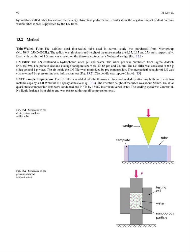
Dent with depth d of 1.5 mm was created on the thin-walled tube by a V-shaped wedge (Fig. 13.1).
LN Filler The LN contained a hydrophobic silica gel and water. The silica gel was purchased from Sigma Aldrich
(No. 60759). The particle size and average nanopore size were 40–63 μm and 7.8 nm. The LN filler was consisted of 0.5 g
silica gel and 1 g water. The air inside the LN filler was minimized by pre-compression. The mechanical behavior of LN was
characterized by pressure-induced infiltration test (Fig. 13.2). The details was reported in ref. [13].
LNFT Sample Preparation The LN filler was added into the thin-walled tube and sealed by attaching both ends with two
metallic caps by a J-B Weld 50,112 epoxy adhesive (Fig. 13.3). The effective height of the tubes was about 20 mm. Uniaxial
quasi-static compression tests were conducted on LNFTs by a 5982 Instron universal tester. The loading speed was 2 mm/min.
No liquid leakage from either end was observed during all compression tests.
Fig. 13.1 Schematic of the
dent creation on thinwalled tube
Fig. 13.2 Schematic of the
pressure-induced
infiltration test
90
M. Li et al.
13.2 Method
Thin-Walled Tube The stainless steel thin-walled tube used in current study was purchased from Microgroup
(No. 304F10500X006SL). The radius, wall thickness and height of the tube samples are 6.35, 0.15 and 25.4 mm, respectively.
Dent with depth d of 1.5 mm was created on the thin-walled tube by a V-shaped wedge (Fig. 13.1).
LN Filler The LN contained a hydrophobic silica gel and water. The silica gel was purchased from Sigma Aldrich
(No. 60759). The particle size and average nanopore size were 40–63 μm and 7.8 nm. The LN filler was consisted of 0.5 g
silica gel and 1 g water. The air inside the LN filler was minimized by pre-compression. The mechanical behavior of LN was
characterized by pressure-induced infiltration test (Fig. 13.2). The details was reported in ref. [13].
LNFT Sample Preparation The LN filler was added into the thin-walled tube and sealed by attaching both ends with two
metallic caps by a J-B Weld 50,112 epoxy adhesive (Fig. 13.3). The effective height of the tubes was about 20 mm. Uniaxial
quasi-static compression tests were conducted on LNFTs by a 5982 Instron universal tester. The loading speed was 2 mm/min.
No liquid leakage from either end was observed during all compression tests.
Fig. 13.1 Schematic of the
dent creation on thinwalled tube
Fig. 13.2 Schematic of the
pressure-induced
infiltration test
90
M. Li et al.