

of an interface from a single test. Additionally, the small size and low inertia of the RDCB specimen make it suitable for high
deformation rate testing. In this study, the RDCB specimen geometry was investigated to characterize the Mode I delamination of a unidirectional E-glass fibre/epoxy laminate.
2.2 Methodology
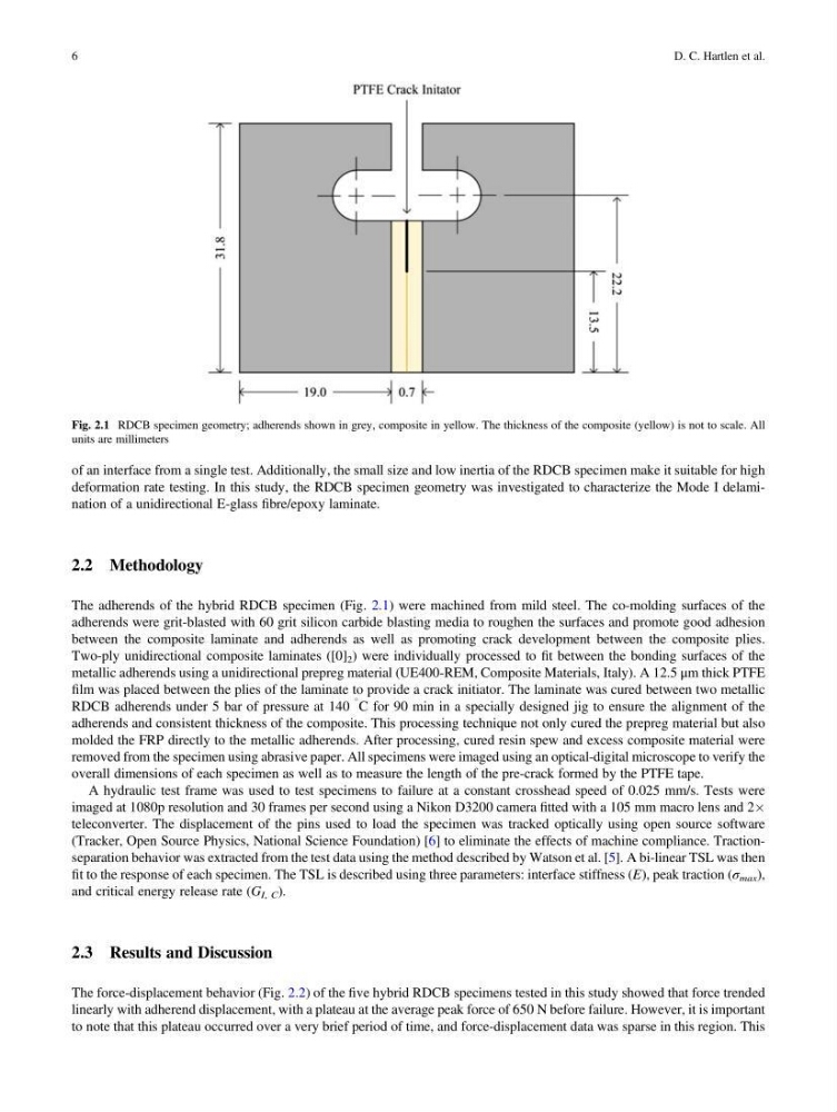
The adherends of the hybrid RDCB specimen (Fig. 2.1) were machined from mild steel. The co-molding surfaces of the
adherends were grit-blasted with 60 grit silicon carbide blasting media to roughen the surfaces and promote good adhesion
between the composite laminate and adherends as well as promoting crack development between the composite plies.
Two-ply unidirectional composite laminates ([0] 2 ) were individually processed to fit between the bonding surfaces of the
metallic adherends using a unidirectional prepreg material (UE400-REM, Composite Materials, Italy). A 12.5 μm thick PTFE
film was placed between the plies of the laminate to provide a crack initiator. The laminate was cured between two metallic
RDCB adherends under 5 bar of pressure at 140
C for 90 min in a specially designed jig to ensure the alignment of the
adherends and consistent thickness of the composite. This processing technique not only cured the prepreg material but also
molded the FRP directly to the metallic adherends. After processing, cured resin spew and excess composite material were
removed from the specimen using abrasive paper. All specimens were imaged using an optical-digital microscope to verify the
overall dimensions of each specimen as well as to measure the length of the pre-crack formed by the PTFE tape.
A hydraulic test frame was used to test specimens to failure at a constant crosshead speed of 0.025 mm/s. Tests were
imaged at 1080p resolution and 30 frames per second using a Nikon D3200 camera fitted with a 105 mm macro lens and 2Â
teleconverter. The displacement of the pins used to load the specimen was tracked optically using open source software
(Tracker, Open Source Physics, National Science Foundation) [6] to eliminate the effects of machine compliance. Tractionseparation behavior was extracted from the test data using the method described by Watson et al. [5]. A bi-linear TSL was then
fit to the response of each specimen. The TSL is described using three parameters: interface stiffness (E), peak traction (σ max ),
and critical energy release rate (G I, C ).
2.3 Results and Discussion
The force-displacement behavior (Fig. 2.2) of the five hybrid RDCB specimens tested in this study showed that force trended
linearly with adherend displacement, with a plateau at the average peak force of 650 N before failure. However, it is important
to note that this plateau occurred over a very brief period of time, and force-displacement data was sparse in this region. This
Fig. 2.1 RDCB specimen geometry; adherends shown in grey, composite in yellow. The thickness of the composite (yellow) is not to scale. All
units are millimeters
6
D. C. Hartlen et al.
deformation rate testing. In this study, the RDCB specimen geometry was investigated to characterize the Mode I delamination of a unidirectional E-glass fibre/epoxy laminate.
2.2 Methodology
The adherends of the hybrid RDCB specimen (Fig. 2.1) were machined from mild steel. The co-molding surfaces of the
adherends were grit-blasted with 60 grit silicon carbide blasting media to roughen the surfaces and promote good adhesion
between the composite laminate and adherends as well as promoting crack development between the composite plies.
Two-ply unidirectional composite laminates ([0] 2 ) were individually processed to fit between the bonding surfaces of the
metallic adherends using a unidirectional prepreg material (UE400-REM, Composite Materials, Italy). A 12.5 μm thick PTFE
film was placed between the plies of the laminate to provide a crack initiator. The laminate was cured between two metallic
RDCB adherends under 5 bar of pressure at 140
C for 90 min in a specially designed jig to ensure the alignment of the
adherends and consistent thickness of the composite. This processing technique not only cured the prepreg material but also
molded the FRP directly to the metallic adherends. After processing, cured resin spew and excess composite material were
removed from the specimen using abrasive paper. All specimens were imaged using an optical-digital microscope to verify the
overall dimensions of each specimen as well as to measure the length of the pre-crack formed by the PTFE tape.
A hydraulic test frame was used to test specimens to failure at a constant crosshead speed of 0.025 mm/s. Tests were
imaged at 1080p resolution and 30 frames per second using a Nikon D3200 camera fitted with a 105 mm macro lens and 2Â
teleconverter. The displacement of the pins used to load the specimen was tracked optically using open source software
(Tracker, Open Source Physics, National Science Foundation) [6] to eliminate the effects of machine compliance. Tractionseparation behavior was extracted from the test data using the method described by Watson et al. [5]. A bi-linear TSL was then
fit to the response of each specimen. The TSL is described using three parameters: interface stiffness (E), peak traction (σ max ),
and critical energy release rate (G I, C ).
2.3 Results and Discussion
The force-displacement behavior (Fig. 2.2) of the five hybrid RDCB specimens tested in this study showed that force trended
linearly with adherend displacement, with a plateau at the average peak force of 650 N before failure. However, it is important
to note that this plateau occurred over a very brief period of time, and force-displacement data was sparse in this region. This
Fig. 2.1 RDCB specimen geometry; adherends shown in grey, composite in yellow. The thickness of the composite (yellow) is not to scale. All
units are millimeters
6
D. C. Hartlen et al.