

15.7 Conclusion
The evidence presented imposes imperative considerations for MFC surface placement on host structures. Parametric studies
performed on a 2-D airfoil displayed significant changes in shape geometry as a function of MFC patch placement. The study
is adapted to a 3-D space where a multi-curved fiber reinforced wing section was observed. In addition to placement,
orientation of MFC actuators and host fibers directly impacted the deflection and curvature of the structure. Modifications to
the boundary surface and host material was shown to influence MFC kinematics. By reducing the restrictive inertia and
stiffness imposed on the MFCs, the overall deflection increased as a result; however, residual effects due to hysteresis become
more prominent. The time-dependent hysteresis profile was also shown to be affected by the multi-stable nature of the
structure. A fundamental flaw in these studies, unfortunately, is the focus on a specific design without generalizing the internal
mechanics of the structure. Additional research is required in order to fully quantify the relation between MFC kinematics and
general structural complexity.
Acknowledgements The authors would like to thank the STTR program under the Air Force Office of Scientific Research for the funding.
References
1. Probst, T., Kochersberger, K., Stiltner, B., Hickling, C., Ohanian, O., Karni, E., Blain, A.: Smart material actuators as a means of UAV flight
control. In: 50th AIAA Aerospace sciences meeting including the new horizons forum and aerospace exposition (2012). https://doi.org/10.2514/
6.2012-486
2. Usher, T.D., Ulibarri, K.R., Camargo, G.S.: Piezoelectric microfiber composite actuators for morphing wings. ISRN Mater. Sci. 2013, 1–8
(2013). https://doi.org/10.1155/2013/189659
3. Lacroix, B.W., Ifju, P.G.: Investigating potential substrates to maximize out-of-plane deflection of piezoelectric macrofiber composite
actuators. J. Intell. Mater. Syst. Struct. 26(7), 781–795 (2014)
4. Lacroix, B.W., Ifju, P.G.: Aeroelastic model for macrofiber composite actuators on micro air vehicles. J. Aircr. 54(1), 199–208 (2017). https://
doi.org/10.2514/1.c032919
5. Sodano, H.A., Park, G., Inman, D.J.: An investigation into the performance of macro-fiber composites for sensing and structural vibration
applications. Mech. Syst. Signal Process. 18(3), 683–697 (2004). https://doi.org/10.1016/s0888-3270(03)00081-5
6. Changhai, R., Lining, S.: Hysteresis and creep compensation for piezoelectric actuator in open-loop operation. Sensors Actuators A Phys. 122
(1), 124–130 (2005). https://doi.org/10.1016/j.sna.2005.03.056
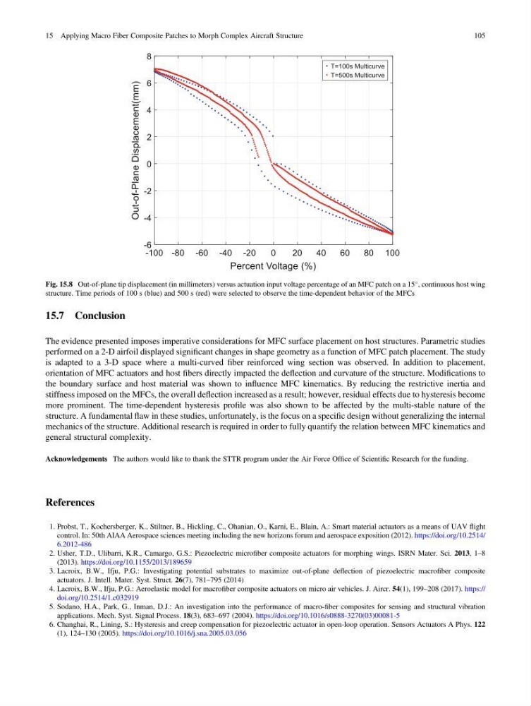
Fig. 15.8 Out-of-plane tip displacement (in millimeters) versus actuation input voltage percentage of an MFC patch on a 15
, continuous host wing
structure. Time periods of 100 s (blue) and 500 s (red) were selected to observe the time-dependent behavior of the MFCs
15 Applying Macro Fiber Composite Patches to Morph Complex Aircraft Structure
105
The evidence presented imposes imperative considerations for MFC surface placement on host structures. Parametric studies
performed on a 2-D airfoil displayed significant changes in shape geometry as a function of MFC patch placement. The study
is adapted to a 3-D space where a multi-curved fiber reinforced wing section was observed. In addition to placement,
orientation of MFC actuators and host fibers directly impacted the deflection and curvature of the structure. Modifications to
the boundary surface and host material was shown to influence MFC kinematics. By reducing the restrictive inertia and
stiffness imposed on the MFCs, the overall deflection increased as a result; however, residual effects due to hysteresis become
more prominent. The time-dependent hysteresis profile was also shown to be affected by the multi-stable nature of the
structure. A fundamental flaw in these studies, unfortunately, is the focus on a specific design without generalizing the internal
mechanics of the structure. Additional research is required in order to fully quantify the relation between MFC kinematics and
general structural complexity.
Acknowledgements The authors would like to thank the STTR program under the Air Force Office of Scientific Research for the funding.
References
1. Probst, T., Kochersberger, K., Stiltner, B., Hickling, C., Ohanian, O., Karni, E., Blain, A.: Smart material actuators as a means of UAV flight
control. In: 50th AIAA Aerospace sciences meeting including the new horizons forum and aerospace exposition (2012). https://doi.org/10.2514/
6.2012-486
2. Usher, T.D., Ulibarri, K.R., Camargo, G.S.: Piezoelectric microfiber composite actuators for morphing wings. ISRN Mater. Sci. 2013, 1–8
(2013). https://doi.org/10.1155/2013/189659
3. Lacroix, B.W., Ifju, P.G.: Investigating potential substrates to maximize out-of-plane deflection of piezoelectric macrofiber composite
actuators. J. Intell. Mater. Syst. Struct. 26(7), 781–795 (2014)
4. Lacroix, B.W., Ifju, P.G.: Aeroelastic model for macrofiber composite actuators on micro air vehicles. J. Aircr. 54(1), 199–208 (2017). https://
doi.org/10.2514/1.c032919
5. Sodano, H.A., Park, G., Inman, D.J.: An investigation into the performance of macro-fiber composites for sensing and structural vibration
applications. Mech. Syst. Signal Process. 18(3), 683–697 (2004). https://doi.org/10.1016/s0888-3270(03)00081-5
6. Changhai, R., Lining, S.: Hysteresis and creep compensation for piezoelectric actuator in open-loop operation. Sensors Actuators A Phys. 122
(1), 124–130 (2005). https://doi.org/10.1016/j.sna.2005.03.056
Fig. 15.8 Out-of-plane tip displacement (in millimeters) versus actuation input voltage percentage of an MFC patch on a 15
, continuous host wing
structure. Time periods of 100 s (blue) and 500 s (red) were selected to observe the time-dependent behavior of the MFCs
15 Applying Macro Fiber Composite Patches to Morph Complex Aircraft Structure
105