

15.5 MFC Patch On A 3-D Complex Wing Geometry
The study adapted to applying an MFC bimorph configuration [3] on a complex 3-D wing surface when varying both fiber
orientation of the host laminate and polarization direction of the MFC. The fiber orientation of the laminate must be parallel to
the polarization direction of the MFC to prevent twisting, which was undesired for this study [17]. The wing was designed
with a complex multi-curved structure and was modeled to have a single bilateral AS4-epoxy ply; properties were tested using
a universal testing machine and applied to an FE model. Placement of the piezoelectric patch was determined prior to this
study through initial investigations done on ABAQUS. Fiber orientations varied with respect to the span, the root to tip vector,
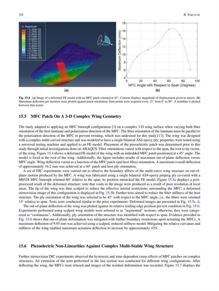
of the wing. Figure 15.4 shows a deformed FE model of the wing with an imbedded MFC patch positioned at a 45
angle. The
model is fixed at the root of the wing. Additionally, the figure includes results of maximum out-of-plane deflection versus
MFC angle. Wing deflection varied as a function of the MFC patch (and host fiber) orientation. A maximum overall deflection
of approximately 16.2 mm was achieved at a 60
patch and host ply orientation.
A set of DIC experiments were carried out to observe the boundary affects of the multi-curve wing structure on out-ofplane motion produced by the MFC. A wing was fabricated using a single bilateral AS4-epoxy prepreg ply co-cured with a
M8528 MFC bimorph oriented 60
relative to the span; its position mimicked the FE model. Figure 15.5a displays a postprocessed result of the deformed structure; note that voids in the image were produced as a result of poor resolution at local
areas. The tip of the wing was then scalped to reduce the effective inertial restrictions surrounding the MFC; a deformed
stereovision image of this configuration is displayed in Fig. 15.5b. Further tests aimed to reduce the fiber stiffness of the host
structure. The ply orientation of the wing was selected to be 45
with respect to the MFC angle, i.e., the fibers were oriented
15
relative to span. Tests were conducted similar to the prior experiments. Deformed images are presented in Fig. 15.5c, d.
The out-of-plane deflection of the wing was plotted against its relative trailing edge position per test condition in Fig. 15.6.
Experiments performed using scalped wing models were referred to as “segmented” sections; otherwise, they were categorized as “continuous”. Additionally, ply orientation of the structure was identified with respect to span. Evidence provided in
Fig. 15.6 shows that out-of-plane deformation was mitigated with further boundary restrictions upon actuating the MFCs. A
maximum deflection of 9.95 mm was achieved using a scalped, reduced stiffness model. Mitigating the relative curvature and
stiffness of the wing enabled maximum actuation deflection to increase by approximately 43%.
15.6 Piezoelectric Non-Linearities Against Complex Multi-Stable Wing Structure
Further stereovision DIC experiments observed the hysteresis and time-dependent creep effects of MFC patches on complex
structures. An extension of the tests performed in the last section was conducted for different wing configurations. After
deflecting the wing, the MFCs were relaxed and images of the residual deformation was recorded. Figure 15.7 displays the
Fig. 15.4 (a) Image of a deformed FE model with an MFC patch oriented at 45
. Contour displays magnitude of displacement given in meters. (b)
Maximum deflection per iteration were plotted against patch orientation. Data points were acquired every 15
from 0
to 90
. A trendline is plotted
between data points
102
B. Tran et al.
The study adapted to applying an MFC bimorph configuration [3] on a complex 3-D wing surface when varying both fiber
orientation of the host laminate and polarization direction of the MFC. The fiber orientation of the laminate must be parallel to
the polarization direction of the MFC to prevent twisting, which was undesired for this study [17]. The wing was designed
with a complex multi-curved structure and was modeled to have a single bilateral AS4-epoxy ply; properties were tested using
a universal testing machine and applied to an FE model. Placement of the piezoelectric patch was determined prior to this
study through initial investigations done on ABAQUS. Fiber orientations varied with respect to the span, the root to tip vector,
of the wing. Figure 15.4 shows a deformed FE model of the wing with an imbedded MFC patch positioned at a 45
angle. The
model is fixed at the root of the wing. Additionally, the figure includes results of maximum out-of-plane deflection versus
MFC angle. Wing deflection varied as a function of the MFC patch (and host fiber) orientation. A maximum overall deflection
of approximately 16.2 mm was achieved at a 60
patch and host ply orientation.
A set of DIC experiments were carried out to observe the boundary affects of the multi-curve wing structure on out-ofplane motion produced by the MFC. A wing was fabricated using a single bilateral AS4-epoxy prepreg ply co-cured with a
M8528 MFC bimorph oriented 60
relative to the span; its position mimicked the FE model. Figure 15.5a displays a postprocessed result of the deformed structure; note that voids in the image were produced as a result of poor resolution at local
areas. The tip of the wing was then scalped to reduce the effective inertial restrictions surrounding the MFC; a deformed
stereovision image of this configuration is displayed in Fig. 15.5b. Further tests aimed to reduce the fiber stiffness of the host
structure. The ply orientation of the wing was selected to be 45
with respect to the MFC angle, i.e., the fibers were oriented
15
relative to span. Tests were conducted similar to the prior experiments. Deformed images are presented in Fig. 15.5c, d.
The out-of-plane deflection of the wing was plotted against its relative trailing edge position per test condition in Fig. 15.6.
Experiments performed using scalped wing models were referred to as “segmented” sections; otherwise, they were categorized as “continuous”. Additionally, ply orientation of the structure was identified with respect to span. Evidence provided in
Fig. 15.6 shows that out-of-plane deformation was mitigated with further boundary restrictions upon actuating the MFCs. A
maximum deflection of 9.95 mm was achieved using a scalped, reduced stiffness model. Mitigating the relative curvature and
stiffness of the wing enabled maximum actuation deflection to increase by approximately 43%.
15.6 Piezoelectric Non-Linearities Against Complex Multi-Stable Wing Structure
Further stereovision DIC experiments observed the hysteresis and time-dependent creep effects of MFC patches on complex
structures. An extension of the tests performed in the last section was conducted for different wing configurations. After
deflecting the wing, the MFCs were relaxed and images of the residual deformation was recorded. Figure 15.7 displays the
Fig. 15.4 (a) Image of a deformed FE model with an MFC patch oriented at 45
. Contour displays magnitude of displacement given in meters. (b)
Maximum deflection per iteration were plotted against patch orientation. Data points were acquired every 15
from 0
to 90
. A trendline is plotted
between data points
102
B. Tran et al.