

4.3 Mixing Optimization of UHPCC and Triaxial Compression Test
79
cast, of which the densities were nearly 2570 kg/m
3 , and the average 120d unconfined cylindrical (50 × 100 mm) compressive strengths were 95 MPa and 129 MPa,
respectively.
4.3.3 Triaxial Compression Test
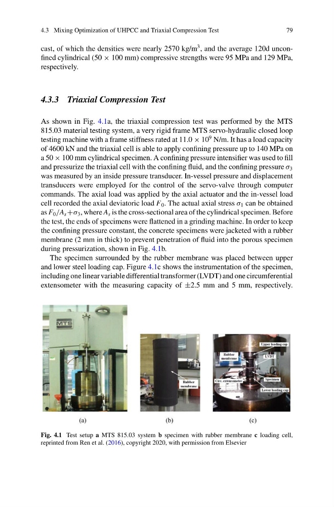
As shown in Fig. 4.1a, the triaxial compression test was performed by the MTS
815.03 material testing system, a very rigid frame MTS servo-hydraulic closed loop
testing machine with a frame stiffness rated at 11.0 × 10
9 N/m. It has a load capacity
of 4600 kN and the triaxial cell is able to apply confining pressure up to 140 MPa on
a 50 × 100 mm cylindrical specimen. A confining pressure intensifier was used to fill
and pressurize the triaxial cell with the confining fluid, and the confining pressure σ 3
was measured by an inside pressure transducer. In-vessel pressure and displacement
transducers were employed for the control of the servo-valve through computer
commands. The axial load was applied by the axial actuator and the in-vessel load
cell recorded the axial deviatoric load F 0 . The actual axial stress σ 1 can be obtained
as F 0 /A s +σ 3 , where A s is the cross-sectional area of the cylindrical specimen. Before
the test, the ends of specimens were flattened in a grinding machine. In order to keep
the confining pressure constant, the concrete specimens were jacketed with a rubber
membrane (2 mm in thick) to prevent penetration of fluid into the porous specimen
during pressurization, shown in Fig. 4.1b.
The specimen surrounded by the rubber membrane was placed between upper
and lower steel loading cap. Figure 4.1c shows the instrumentation of the specimen,
including one linear variable differential transformer (LVDT) and one circumferential
extensometer with the measuring capacity of ±2.5 mm and 5 mm, respectively.
Fig. 4.1 Test setup a MTS 815.03 system b specimen with rubber membrane c loading cell,
reprinted from Ren et al. (2016), copyright 2020, with permission from Elsevier
79
cast, of which the densities were nearly 2570 kg/m
3 , and the average 120d unconfined cylindrical (50 × 100 mm) compressive strengths were 95 MPa and 129 MPa,
respectively.
4.3.3 Triaxial Compression Test
As shown in Fig. 4.1a, the triaxial compression test was performed by the MTS
815.03 material testing system, a very rigid frame MTS servo-hydraulic closed loop
testing machine with a frame stiffness rated at 11.0 × 10
9 N/m. It has a load capacity
of 4600 kN and the triaxial cell is able to apply confining pressure up to 140 MPa on
a 50 × 100 mm cylindrical specimen. A confining pressure intensifier was used to fill
and pressurize the triaxial cell with the confining fluid, and the confining pressure σ 3
was measured by an inside pressure transducer. In-vessel pressure and displacement
transducers were employed for the control of the servo-valve through computer
commands. The axial load was applied by the axial actuator and the in-vessel load
cell recorded the axial deviatoric load F 0 . The actual axial stress σ 1 can be obtained
as F 0 /A s +σ 3 , where A s is the cross-sectional area of the cylindrical specimen. Before
the test, the ends of specimens were flattened in a grinding machine. In order to keep
the confining pressure constant, the concrete specimens were jacketed with a rubber
membrane (2 mm in thick) to prevent penetration of fluid into the porous specimen
during pressurization, shown in Fig. 4.1b.
The specimen surrounded by the rubber membrane was placed between upper
and lower steel loading cap. Figure 4.1c shows the instrumentation of the specimen,
including one linear variable differential transformer (LVDT) and one circumferential
extensometer with the measuring capacity of ±2.5 mm and 5 mm, respectively.
Fig. 4.1 Test setup a MTS 815.03 system b specimen with rubber membrane c loading cell,
reprinted from Ren et al. (2016), copyright 2020, with permission from Elsevier