

482
14 Constitutive Modelling of UHPCC Material Under Impact …
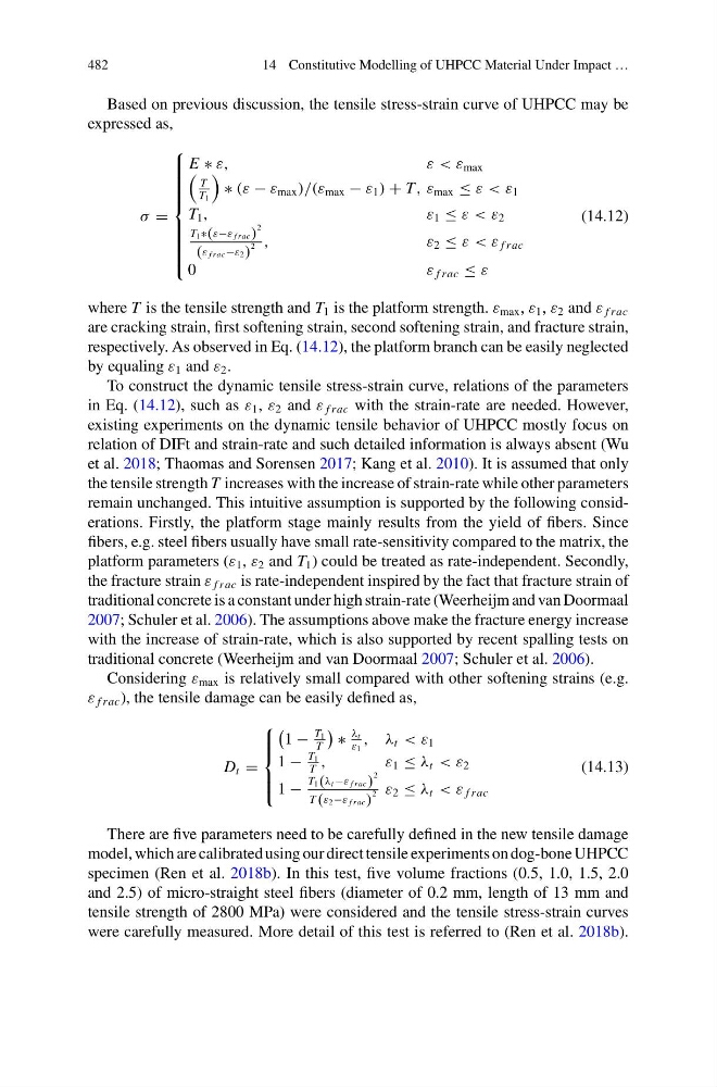
Based on previous discussion, the tensile stress-strain curve of UHPCC may be
expressed as,
σ =
⎧
⎪ ⎪ ⎪ ⎪ ⎪ ⎪ ⎪ ⎨
⎪ ⎪ ⎪ ⎪ ⎪ ⎪ ⎪ ⎩
E ∗ ε,
ε < ε max
T
T 1
∗ (ε − ε max )/(ε max − ε 1 ) + T, ε max ≤ ε < ε 1
T 1 ,
ε 1 ≤ ε < ε 2
T 1 ∗(ε−ε f rac)
2
(ε f rac −ε 2 )
2 ,
ε 2 ≤ ε < ε f rac
0
ε f rac ≤ ε
(14.12)
where T is the tensile strength and T 1 is the platform strength. ε max , ε 1 , ε 2 and ε f rac
are cracking strain, first softening strain, second softening strain, and fracture strain,
respectively. As observed in Eq. (14.12), the platform branch can be easily neglected
by equaling ε 1 and ε 2 .
To construct the dynamic tensile stress-strain curve, relations of the parameters
in Eq. (14.12), such as ε 1 , ε 2 and ε f rac with the strain-rate are needed. However,
existing experiments on the dynamic tensile behavior of UHPCC mostly focus on
relation of DIFt and strain-rate and such detailed information is always absent (Wu
et al. 2018; Thaomas and Sorensen 2017; Kang et al. 2010). It is assumed that only
the tensile strength T increases with the increase of strain-rate while other parameters
remain unchanged. This intuitive assumption is supported by the following considerations. Firstly, the platform stage mainly results from the yield of fibers. Since
fibers, e.g. steel fibers usually have small rate-sensitivity compared to the matrix, the
platform parameters (ε 1 , ε 2 and T 1 ) could be treated as rate-independent. Secondly,
the fracture strain ε f rac is rate-independent inspired by the fact that fracture strain of
traditional concrete is a constant under high strain-rate (Weerheijm and van Doormaal
2007; Schuler et al. 2006). The assumptions above make the fracture energy increase
with the increase of strain-rate, which is also supported by recent spalling tests on
traditional concrete (Weerheijm and van Doormaal 2007; Schuler et al. 2006).
Considering ε max is relatively small compared with other softening strains (e.g.
ε f rac ), the tensile damage can be easily defined as,
D t =
⎧
⎪ ⎪ ⎨
⎪ ⎪ ⎩
1 −
T 1
T
∗
λ t
ε 1
, λ t < ε 1
1 −
T 1
T
,
ε 1 ≤ λ t < ε 2
1 −
T 1( λ t −ε f rac)
2
T (ε2−ε f rac)
2 ε 2 ≤ λ t < ε f rac
(14.13)
There are five parameters need to be carefully defined in the new tensile damage
model, which are calibrated using our direct tensile experiments on dog-bone UHPCC
specimen (Ren et al. 2018b). In this test, five volume fractions (0.5, 1.0, 1.5, 2.0
and 2.5) of micro-straight steel fibers (diameter of 0.2 mm, length of 13 mm and
tensile strength of 2800 MPa) were considered and the tensile stress-strain curves
were carefully measured. More detail of this test is referred to (Ren et al. 2018b).
14 Constitutive Modelling of UHPCC Material Under Impact …
Based on previous discussion, the tensile stress-strain curve of UHPCC may be
expressed as,
σ =
⎧
⎪ ⎪ ⎪ ⎪ ⎪ ⎪ ⎪ ⎨
⎪ ⎪ ⎪ ⎪ ⎪ ⎪ ⎪ ⎩
E ∗ ε,
ε < ε max
T
T 1
∗ (ε − ε max )/(ε max − ε 1 ) + T, ε max ≤ ε < ε 1
T 1 ,
ε 1 ≤ ε < ε 2
T 1 ∗(ε−ε f rac)
2
(ε f rac −ε 2 )
2 ,
ε 2 ≤ ε < ε f rac
0
ε f rac ≤ ε
(14.12)
where T is the tensile strength and T 1 is the platform strength. ε max , ε 1 , ε 2 and ε f rac
are cracking strain, first softening strain, second softening strain, and fracture strain,
respectively. As observed in Eq. (14.12), the platform branch can be easily neglected
by equaling ε 1 and ε 2 .
To construct the dynamic tensile stress-strain curve, relations of the parameters
in Eq. (14.12), such as ε 1 , ε 2 and ε f rac with the strain-rate are needed. However,
existing experiments on the dynamic tensile behavior of UHPCC mostly focus on
relation of DIFt and strain-rate and such detailed information is always absent (Wu
et al. 2018; Thaomas and Sorensen 2017; Kang et al. 2010). It is assumed that only
the tensile strength T increases with the increase of strain-rate while other parameters
remain unchanged. This intuitive assumption is supported by the following considerations. Firstly, the platform stage mainly results from the yield of fibers. Since
fibers, e.g. steel fibers usually have small rate-sensitivity compared to the matrix, the
platform parameters (ε 1 , ε 2 and T 1 ) could be treated as rate-independent. Secondly,
the fracture strain ε f rac is rate-independent inspired by the fact that fracture strain of
traditional concrete is a constant under high strain-rate (Weerheijm and van Doormaal
2007; Schuler et al. 2006). The assumptions above make the fracture energy increase
with the increase of strain-rate, which is also supported by recent spalling tests on
traditional concrete (Weerheijm and van Doormaal 2007; Schuler et al. 2006).
Considering ε max is relatively small compared with other softening strains (e.g.
ε f rac ), the tensile damage can be easily defined as,
D t =
⎧
⎪ ⎪ ⎨
⎪ ⎪ ⎩
1 −
T 1
T
∗
λ t
ε 1
, λ t < ε 1
1 −
T 1
T
,
ε 1 ≤ λ t < ε 2
1 −
T 1( λ t −ε f rac)
2
T (ε2−ε f rac)
2 ε 2 ≤ λ t < ε f rac
(14.13)
There are five parameters need to be carefully defined in the new tensile damage
model, which are calibrated using our direct tensile experiments on dog-bone UHPCC
specimen (Ren et al. 2018b). In this test, five volume fractions (0.5, 1.0, 1.5, 2.0
and 2.5) of micro-straight steel fibers (diameter of 0.2 mm, length of 13 mm and
tensile strength of 2800 MPa) were considered and the tensile stress-strain curves
were carefully measured. More detail of this test is referred to (Ren et al. 2018b).