

386
11 Experimental and Numerical Study of UHPCC-FST Columns …
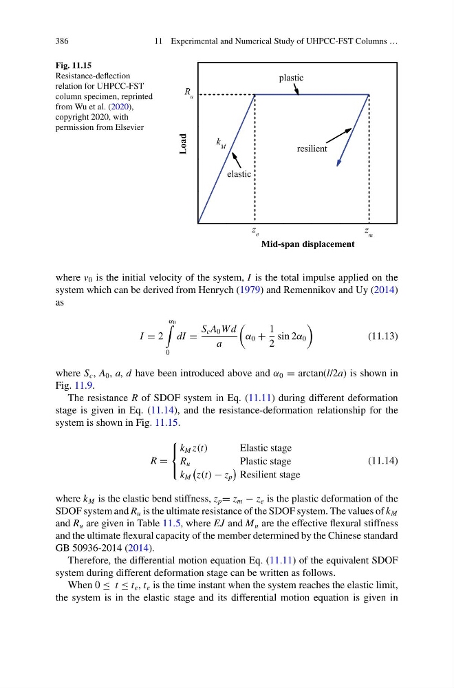
Fig. 11.15
Resistance-deflection
relation for UHPCC-FST
column specimen, reprinted
from Wu et al. (2020),
copyright 2020, with
permission from Elsevier
resilient
k M
plastic
Mid-span displacement
z m
R u
z e
elastic
Load
where v 0 is the initial velocity of the system, I is the total impulse applied on the
system which can be derived from Henrych (1979) and Remennikov and Uy (2014)
as
I = 2
α 0
0
dI =
S c A 0 W d
a
α 0 +
1
2
sin 2α 0
(11.13)
where S c , A 0 , a, d have been introduced above and α 0 = arctan(l/2a) is shown in
Fig. 11.9.
The resistance R of SDOF system in Eq. (11.11) during different deformation
stage is given in Eq. (11.14), and the resistance-deformation relationship for the
system is shown in Fig. 11.15.
R =
⎧
⎨
⎩
k M z(t)
Elastic stage
R u
Plastic stage
k M
z(t) − z p
Resilient stage
(11.14)
where k M is the elastic bend stiffness, z p = z m − z e is the plastic deformation of the
SDOF system and R u is the ultimate resistance of the SDOF system. The values of k M
and R u are given in Table 11.5, where EJ and M u are the effective flexural stiffness
and the ultimate flexural capacity of the member determined by the Chinese standard
GB 50936-2014 (2014).
Therefore, the differential motion equation Eq. (11.11) of the equivalent SDOF
system during different deformation stage can be written as follows.
When 0 ≤ t ≤ t e , t e is the time instant when the system reaches the elastic limit,
the system is in the elastic stage and its differential motion equation is given in
11 Experimental and Numerical Study of UHPCC-FST Columns …
Fig. 11.15
Resistance-deflection
relation for UHPCC-FST
column specimen, reprinted
from Wu et al. (2020),
copyright 2020, with
permission from Elsevier
resilient
k M
plastic
Mid-span displacement
z m
R u
z e
elastic
Load
where v 0 is the initial velocity of the system, I is the total impulse applied on the
system which can be derived from Henrych (1979) and Remennikov and Uy (2014)
as
I = 2
α 0
0
dI =
S c A 0 W d
a
α 0 +
1
2
sin 2α 0
(11.13)
where S c , A 0 , a, d have been introduced above and α 0 = arctan(l/2a) is shown in
Fig. 11.9.
The resistance R of SDOF system in Eq. (11.11) during different deformation
stage is given in Eq. (11.14), and the resistance-deformation relationship for the
system is shown in Fig. 11.15.
R =
⎧
⎨
⎩
k M z(t)
Elastic stage
R u
Plastic stage
k M
z(t) − z p
Resilient stage
(11.14)
where k M is the elastic bend stiffness, z p = z m − z e is the plastic deformation of the
SDOF system and R u is the ultimate resistance of the SDOF system. The values of k M
and R u are given in Table 11.5, where EJ and M u are the effective flexural stiffness
and the ultimate flexural capacity of the member determined by the Chinese standard
GB 50936-2014 (2014).
Therefore, the differential motion equation Eq. (11.11) of the equivalent SDOF
system during different deformation stage can be written as follows.
When 0 ≤ t ≤ t e , t e is the time instant when the system reaches the elastic limit,
the system is in the elastic stage and its differential motion equation is given in