

10.6 Numerical Simulation
343
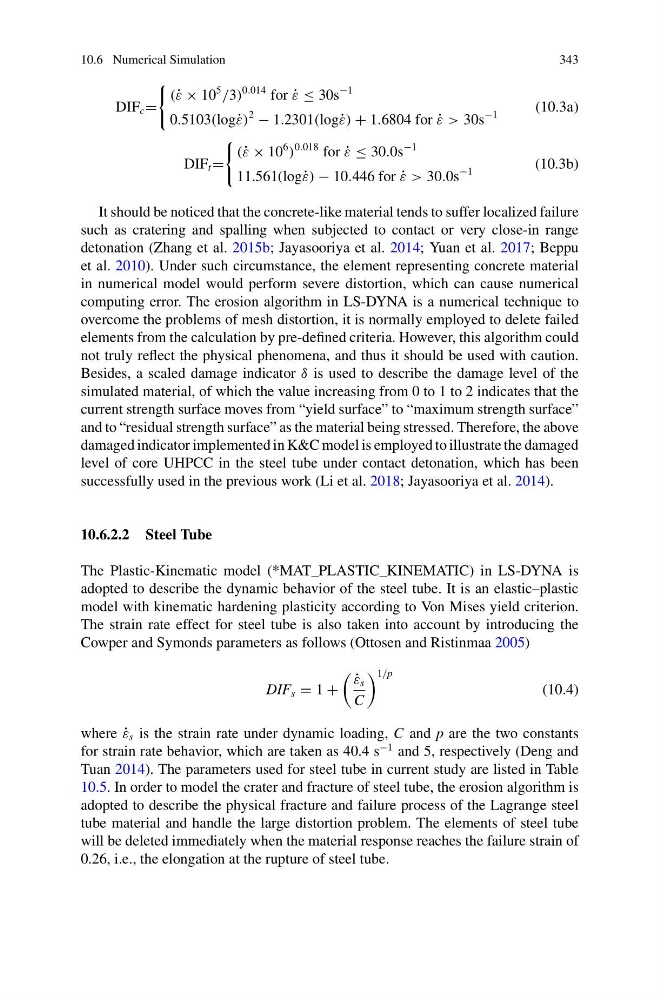
DIF c =
(˙ ε × 10
5
/3)
0.014 for ˙
ε ≤ 30s
−1
0.5103(log˙ ε)
2
− 1.2301(log˙ ε) + 1.6804 for ˙
ε > 30s
−1
(10.3a)
DIF t =
(˙ ε × 10
6
)
0.018 for ˙
ε ≤ 30.0s
−1
11.561(log˙ ε) − 10.446 for ˙
ε > 30.0s
−1
(10.3b)
It should be noticed that the concrete-like material tends to suffer localized failure
such as cratering and spalling when subjected to contact or very close-in range
detonation (Zhang et al. 2015b; Jayasooriya et al. 2014; Yuan et al. 2017; Beppu
et al. 2010). Under such circumstance, the element representing concrete material
in numerical model would perform severe distortion, which can cause numerical
computing error. The erosion algorithm in LS-DYNA is a numerical technique to
overcome the problems of mesh distortion, it is normally employed to delete failed
elements from the calculation by pre-defined criteria. However, this algorithm could
not truly reflect the physical phenomena, and thus it should be used with caution.
Besides, a scaled damage indicator δ is used to describe the damage level of the
simulated material, of which the value increasing from 0 to 1 to 2 indicates that the
current strength surface moves from “yield surface” to “maximum strength surface”
and to “residual strength surface” as the material being stressed. Therefore, the above
damaged indicator implemented in K&C model is employed to illustrate the damaged
level of core UHPCC in the steel tube under contact detonation, which has been
successfully used in the previous work (Li et al. 2018; Jayasooriya et al. 2014).
10.6.2.2 Steel Tube
The Plastic-Kinematic model (*MAT_PLASTIC_KINEMATIC) in LS-DYNA is
adopted to describe the dynamic behavior of the steel tube. It is an elastic–plastic
model with kinematic hardening plasticity according to Von Mises yield criterion.
The strain rate effect for steel tube is also taken into account by introducing the
Cowper and Symonds parameters as follows (Ottosen and Ristinmaa 2005)
DIF s = 1 +
˙
ε s
C
1/p
(10.4)
where ˙
ε s is the strain rate under dynamic loading, C and p are the two constants
for strain rate behavior, which are taken as 40.4 s
−1 and 5, respectively (Deng and
Tuan 2014). The parameters used for steel tube in current study are listed in Table
10.5. In order to model the crater and fracture of steel tube, the erosion algorithm is
adopted to describe the physical fracture and failure process of the Lagrange steel
tube material and handle the large distortion problem. The elements of steel tube
will be deleted immediately when the material response reaches the failure strain of
0.26, i.e., the elongation at the rupture of steel tube.
343
DIF c =
(˙ ε × 10
5
/3)
0.014 for ˙
ε ≤ 30s
−1
0.5103(log˙ ε)
2
− 1.2301(log˙ ε) + 1.6804 for ˙
ε > 30s
−1
(10.3a)
DIF t =
(˙ ε × 10
6
)
0.018 for ˙
ε ≤ 30.0s
−1
11.561(log˙ ε) − 10.446 for ˙
ε > 30.0s
−1
(10.3b)
It should be noticed that the concrete-like material tends to suffer localized failure
such as cratering and spalling when subjected to contact or very close-in range
detonation (Zhang et al. 2015b; Jayasooriya et al. 2014; Yuan et al. 2017; Beppu
et al. 2010). Under such circumstance, the element representing concrete material
in numerical model would perform severe distortion, which can cause numerical
computing error. The erosion algorithm in LS-DYNA is a numerical technique to
overcome the problems of mesh distortion, it is normally employed to delete failed
elements from the calculation by pre-defined criteria. However, this algorithm could
not truly reflect the physical phenomena, and thus it should be used with caution.
Besides, a scaled damage indicator δ is used to describe the damage level of the
simulated material, of which the value increasing from 0 to 1 to 2 indicates that the
current strength surface moves from “yield surface” to “maximum strength surface”
and to “residual strength surface” as the material being stressed. Therefore, the above
damaged indicator implemented in K&C model is employed to illustrate the damaged
level of core UHPCC in the steel tube under contact detonation, which has been
successfully used in the previous work (Li et al. 2018; Jayasooriya et al. 2014).
10.6.2.2 Steel Tube
The Plastic-Kinematic model (*MAT_PLASTIC_KINEMATIC) in LS-DYNA is
adopted to describe the dynamic behavior of the steel tube. It is an elastic–plastic
model with kinematic hardening plasticity according to Von Mises yield criterion.
The strain rate effect for steel tube is also taken into account by introducing the
Cowper and Symonds parameters as follows (Ottosen and Ristinmaa 2005)
DIF s = 1 +
˙
ε s
C
1/p
(10.4)
where ˙
ε s is the strain rate under dynamic loading, C and p are the two constants
for strain rate behavior, which are taken as 40.4 s
−1 and 5, respectively (Deng and
Tuan 2014). The parameters used for steel tube in current study are listed in Table
10.5. In order to model the crater and fracture of steel tube, the erosion algorithm is
adopted to describe the physical fracture and failure process of the Lagrange steel
tube material and handle the large distortion problem. The elements of steel tube
will be deleted immediately when the material response reaches the failure strain of
0.26, i.e., the elongation at the rupture of steel tube.