

326
10 Residual Axial Capacity of UHPCC-FST Column Under …
Support
TNT charge
Support
Specimen
(a)
Support
Support
Specimen
1900
(b)
TNT charge
Detonator
1kg
2kg
3kg
95
116
92
121
(c)
(d)
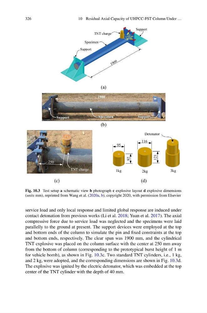
Fig. 10.3 Test setup a schematic view b photograph c explosive layout d explosive dimensions
(units mm), reprinted from Wang et al. (2020a, b), copyright 2020, with permission from Elsevier
service load and only local response and limited global response are induced under
contact detonation from previous works (Li et al. 2018; Yuan et al. 2017). The axial
compressive force due to service load was neglected and the specimens were laid
parallelly to the ground at present. The support devices were employed at the top
and bottom ends of the column to simulate the pin and fixed constraints at the top
and bottom ends, respectively. The clear span was 1900 mm, and the cylindrical
TNT explosive was placed on the column surface with the center at 250 mm away
from the bottom of column (corresponding to the prototypical burst height of 1 m
for vehicle bomb), as shown in Fig. 10.3c. Two standard TNT cylinders, i.e., 1 kg,
and 2 kg, were adopted, and the corresponding dimensions are shown in Fig. 10.3d.
The explosive was ignited by the electric detonator, which was embedded at the top
center of the TNT cylinder with the depth of 40 mm.
10 Residual Axial Capacity of UHPCC-FST Column Under …
Support
TNT charge
Support
Specimen
(a)
Support
Support
Specimen
1900
(b)
TNT charge
Detonator
1kg
2kg
3kg
95
116
92
121
(c)
(d)
Fig. 10.3 Test setup a schematic view b photograph c explosive layout d explosive dimensions
(units mm), reprinted from Wang et al. (2020a, b), copyright 2020, with permission from Elsevier
service load and only local response and limited global response are induced under
contact detonation from previous works (Li et al. 2018; Yuan et al. 2017). The axial
compressive force due to service load was neglected and the specimens were laid
parallelly to the ground at present. The support devices were employed at the top
and bottom ends of the column to simulate the pin and fixed constraints at the top
and bottom ends, respectively. The clear span was 1900 mm, and the cylindrical
TNT explosive was placed on the column surface with the center at 250 mm away
from the bottom of column (corresponding to the prototypical burst height of 1 m
for vehicle bomb), as shown in Fig. 10.3c. Two standard TNT cylinders, i.e., 1 kg,
and 2 kg, were adopted, and the corresponding dimensions are shown in Fig. 10.3d.
The explosive was ignited by the electric detonator, which was embedded at the top
center of the TNT cylinder with the depth of 40 mm.