

9.5 Further Validations
311
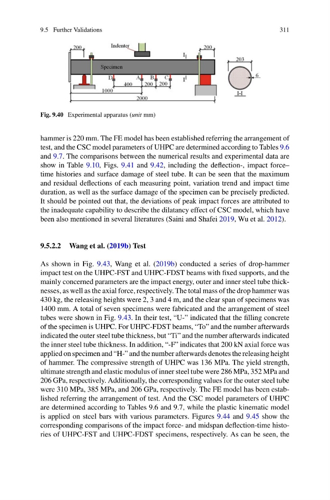
Fig. 9.40 Experimental apparatus (unit mm)
hammer is 220 mm. The FE model has been established referring the arrangement of
test, and the CSC model parameters of UHPC are determined according to Tables 9.6
and 9.7. The comparisons between the numerical results and experimental data are
show in Table 9.10, Figs. 9.41 and 9.42, including the deflection-, impact force–
time histories and surface damage of steel tube. It can be seen that the maximum
and residual deflections of each measuring point, variation trend and impact time
duration, as well as the surface damage of the specimen can be precisely predicted.
It should be pointed out that, the deviations of peak impact forces are attributed to
the inadequate capability to describe the dilatancy effect of CSC model, which have
been also mentioned in several literatures (Saini and Shafei 2019, Wu et al. 2012).
9.5.2.2 Wang et al. (2019b) Test
As shown in Fig. 9.43, Wang et al. (2019b) conducted a series of drop-hammer
impact test on the UHPC-FST and UHPC-FDST beams with fixed supports, and the
mainly concerned parameters are the impact energy, outer and inner steel tube thicknesses, as well as the axial force, respectively. The total mass of the drop hammer was
430 kg, the releasing heights were 2, 3 and 4 m, and the clear span of specimens was
1400 mm. A total of seven specimens were fabricated and the arrangement of steel
tubes were shown in Fig. 9.43. In their test, “U-” indicated that the filling concrete
of the specimen is UHPC. For UHPC-FDST beams, “To” and the number afterwards
indicated the outer steel tube thickness, but “Ti” and the number afterwards indicated
the inner steel tube thickness. In addition, “-F” indicates that 200 kN axial force was
applied on specimen and “H-” and the number afterwards denotes the releasing height
of hammer. The compressive strength of UHPC was 136 MPa. The yield strength,
ultimate strength and elastic modulus of inner steel tube were 286 MPa, 352 MPa and
206 GPa, respectively. Additionally, the corresponding values for the outer steel tube
were 310 MPa, 385 MPa, and 206 GPa, respectively. The FE model has been established referring the arrangement of test. And the CSC model parameters of UHPC
are determined according to Tables 9.6 and 9.7, while the plastic kinematic model
is applied on steel bars with various parameters. Figures 9.44 and 9.45 show the
corresponding comparisons of the impact force- and midspan deflection-time histories of UHPC-FST and UHPC-FDST specimens, respectively. As can be seen, the
311
Fig. 9.40 Experimental apparatus (unit mm)
hammer is 220 mm. The FE model has been established referring the arrangement of
test, and the CSC model parameters of UHPC are determined according to Tables 9.6
and 9.7. The comparisons between the numerical results and experimental data are
show in Table 9.10, Figs. 9.41 and 9.42, including the deflection-, impact force–
time histories and surface damage of steel tube. It can be seen that the maximum
and residual deflections of each measuring point, variation trend and impact time
duration, as well as the surface damage of the specimen can be precisely predicted.
It should be pointed out that, the deviations of peak impact forces are attributed to
the inadequate capability to describe the dilatancy effect of CSC model, which have
been also mentioned in several literatures (Saini and Shafei 2019, Wu et al. 2012).
9.5.2.2 Wang et al. (2019b) Test
As shown in Fig. 9.43, Wang et al. (2019b) conducted a series of drop-hammer
impact test on the UHPC-FST and UHPC-FDST beams with fixed supports, and the
mainly concerned parameters are the impact energy, outer and inner steel tube thicknesses, as well as the axial force, respectively. The total mass of the drop hammer was
430 kg, the releasing heights were 2, 3 and 4 m, and the clear span of specimens was
1400 mm. A total of seven specimens were fabricated and the arrangement of steel
tubes were shown in Fig. 9.43. In their test, “U-” indicated that the filling concrete
of the specimen is UHPC. For UHPC-FDST beams, “To” and the number afterwards
indicated the outer steel tube thickness, but “Ti” and the number afterwards indicated
the inner steel tube thickness. In addition, “-F” indicates that 200 kN axial force was
applied on specimen and “H-” and the number afterwards denotes the releasing height
of hammer. The compressive strength of UHPC was 136 MPa. The yield strength,
ultimate strength and elastic modulus of inner steel tube were 286 MPa, 352 MPa and
206 GPa, respectively. Additionally, the corresponding values for the outer steel tube
were 310 MPa, 385 MPa, and 206 GPa, respectively. The FE model has been established referring the arrangement of test. And the CSC model parameters of UHPC
are determined according to Tables 9.6 and 9.7, while the plastic kinematic model
is applied on steel bars with various parameters. Figures 9.44 and 9.45 show the
corresponding comparisons of the impact force- and midspan deflection-time histories of UHPC-FST and UHPC-FDST specimens, respectively. As can be seen, the