

9.5 Further Validations
305
Table 9.8 Experiments of further validation
References
Specimen type f
c (MPa) Length (mm) Boundary Axial force (kN)
Fujikake et al.
(2006)
UHPC beam
214.7
1700
Simply
supported
0
Yoo et al.
(2015)
UHPC beam
152.5
2900
Fixed
supported
0
Fan et al.
(2019)
UHPC column 155
2200
Sliding
supported
0/400
Wu et al.
(2019)
UHPC-FST
141.5
2000
Simply
supported
0
Wang et al.
(2019b)
UHPC-FST
136
2000
Fixed
supported
0/200
UHPC-FDST
Wei et al.
(2019)
UHPC column 136
2000
Fixed
supported
200
9.5.1 Reinforced UHPC Members
9.5.1.1 Fujikake et al. (2006) Test
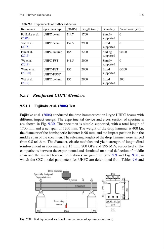
Fujikake et al. (2006) conducted the drop hammer test on I-type UHPC beams with
different impact energy. The experimental device and cross section of specimens
are shown in Fig. 9.30. The specimen is simple supported, with a total length of
1700 mm and a net span of 1200 mm. The weight of the drop hammer is 400 kg,
the diameter of the hemispheric indenter is 90 mm, and the impact position is in the
middle span of the specimen. The releasing heights of the drop hammer were ranged
from 0.8 to1.6 m. The diameter, elastic modulus and yield strength of longitudinal
reinforcement in specimens are 13 mm, 200 GPa and 295 MPa, respectively. The
comparisons between the experimental and simulated maximal deflection of middle
span and the impact force–time histories are given in Table 9.9 and Fig. 9.31, in
which the CSC model parameters for UHPC are determined from Tables 9.6 and
Fig. 9.30 Test layout and sectional reinforcement of specimen (unit mm)
305
Table 9.8 Experiments of further validation
References
Specimen type f
c (MPa) Length (mm) Boundary Axial force (kN)
Fujikake et al.
(2006)
UHPC beam
214.7
1700
Simply
supported
0
Yoo et al.
(2015)
UHPC beam
152.5
2900
Fixed
supported
0
Fan et al.
(2019)
UHPC column 155
2200
Sliding
supported
0/400
Wu et al.
(2019)
UHPC-FST
141.5
2000
Simply
supported
0
Wang et al.
(2019b)
UHPC-FST
136
2000
Fixed
supported
0/200
UHPC-FDST
Wei et al.
(2019)
UHPC column 136
2000
Fixed
supported
200
9.5.1 Reinforced UHPC Members
9.5.1.1 Fujikake et al. (2006) Test
Fujikake et al. (2006) conducted the drop hammer test on I-type UHPC beams with
different impact energy. The experimental device and cross section of specimens
are shown in Fig. 9.30. The specimen is simple supported, with a total length of
1700 mm and a net span of 1200 mm. The weight of the drop hammer is 400 kg,
the diameter of the hemispheric indenter is 90 mm, and the impact position is in the
middle span of the specimen. The releasing heights of the drop hammer were ranged
from 0.8 to1.6 m. The diameter, elastic modulus and yield strength of longitudinal
reinforcement in specimens are 13 mm, 200 GPa and 295 MPa, respectively. The
comparisons between the experimental and simulated maximal deflection of middle
span and the impact force–time histories are given in Table 9.9 and Fig. 9.31, in
which the CSC model parameters for UHPC are determined from Tables 9.6 and
Fig. 9.30 Test layout and sectional reinforcement of specimen (unit mm)