

286
9 Dynamic Responses of Reinforced UHPCC Members Under …
-80
-60
-40
-20
0
Sliding end
E
D
C
B
A
Fixed end
Deflection
(mm)
Tracing point
5ms
10ms
20ms
30ms
50ms
-80
-60
-40
-20
0
Sliding end
E
D
C
B
A
Fixed end
Deflection (mm)
Tracing point
5ms
10ms
20ms
30ms
50ms
-30
-20
-10
0
Sliding end
E
D
C
B
A
Fixed end
Deflection (mm)
Tracing point
2.5ms
5ms
7.5ms
10ms
20ms
(a)
(b)
(c)
-40
-30
-20
-10
0
Sliding end
E
D
C
B
A
Fixed end
Deflection
(mm)
Tracing point
2.5ms
5ms
7.5ms
10ms
20ms
(d)
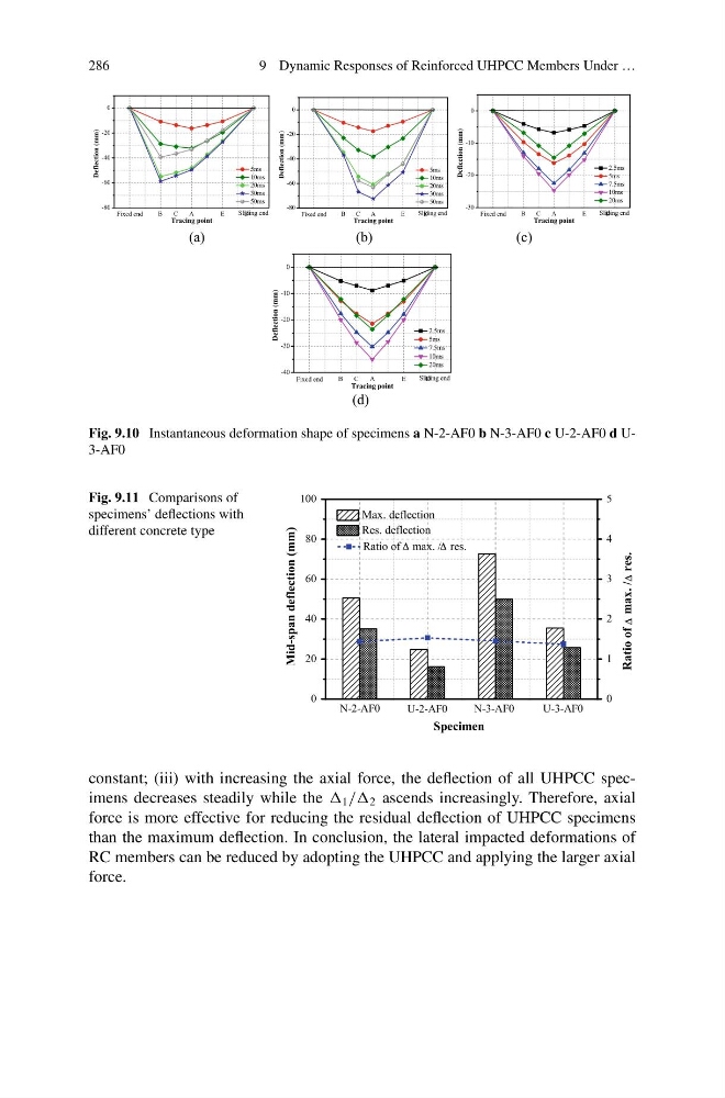
Fig. 9.10 Instantaneous deformation shape of specimens a N-2-AF0 b N-3-AF0 c U-2-AF0 d U3-AF0
Fig. 9.11 Comparisons of
specimens’ deflections with
different concrete type
0
20
40
60
80
100
Mid-span deflection (mm)
U-3-AF0
N-3-AF0
U-2-AF0
N-2-AF0
Max. deflection
Res. deflection
Specimen
Ratio of
max. / res.
0
1
2
3
4
5
Ratio of max. / res.
constant; (iii) with increasing the axial force, the deflection of all UHPCC specimens decreases steadily while the 1 // 2 ascends increasingly. Therefore, axial
force is more effective for reducing the residual deflection of UHPCC specimens
than the maximum deflection. In conclusion, the lateral impacted deformations of
RC members can be reduced by adopting the UHPCC and applying the larger axial
force.
9 Dynamic Responses of Reinforced UHPCC Members Under …
-80
-60
-40
-20
0
Sliding end
E
D
C
B
A
Fixed end
Deflection
(mm)
Tracing point
5ms
10ms
20ms
30ms
50ms
-80
-60
-40
-20
0
Sliding end
E
D
C
B
A
Fixed end
Deflection (mm)
Tracing point
5ms
10ms
20ms
30ms
50ms
-30
-20
-10
0
Sliding end
E
D
C
B
A
Fixed end
Deflection (mm)
Tracing point
2.5ms
5ms
7.5ms
10ms
20ms
(a)
(b)
(c)
-40
-30
-20
-10
0
Sliding end
E
D
C
B
A
Fixed end
Deflection
(mm)
Tracing point
2.5ms
5ms
7.5ms
10ms
20ms
(d)
Fig. 9.10 Instantaneous deformation shape of specimens a N-2-AF0 b N-3-AF0 c U-2-AF0 d U3-AF0
Fig. 9.11 Comparisons of
specimens’ deflections with
different concrete type
0
20
40
60
80
100
Mid-span deflection (mm)
U-3-AF0
N-3-AF0
U-2-AF0
N-2-AF0
Max. deflection
Res. deflection
Specimen
Ratio of
max. / res.
0
1
2
3
4
5
Ratio of max. / res.
constant; (iii) with increasing the axial force, the deflection of all UHPCC specimens decreases steadily while the 1 // 2 ascends increasingly. Therefore, axial
force is more effective for reducing the residual deflection of UHPCC specimens
than the maximum deflection. In conclusion, the lateral impacted deformations of
RC members can be reduced by adopting the UHPCC and applying the larger axial
force.