

1.3 Instrumentation and Loading Scheme
7
testing machine was used, which consisted of a stiff loading frame with 3000kN
load cell and the loading rate was set as 0.1 mm/min. One linear variable differential
transformer (LVDT) and two laser displacement sensors positioned at opposite sides
of the specimens were used to record the overall axial displacement of testing machine
and the averaged overall axial displacement of specimens, respectively. Three sets
of mutually perpendicular strain gauges attached on the surface of specimens were
used to measure the averaged local axial and circumferential strains of specimens.
Since the strain gauges attached on the surface of specimens would come off at
the peak strength due to the spalling of concrete, the strain data recorded by the
strain gauges and laser displacement sensors were respectively used for the pre-peak
and post-cracking stages of the full compressive stress–strain curves, as shown in
Sect. 1.4.1.2.
1.3.3 Direct Tensile Test
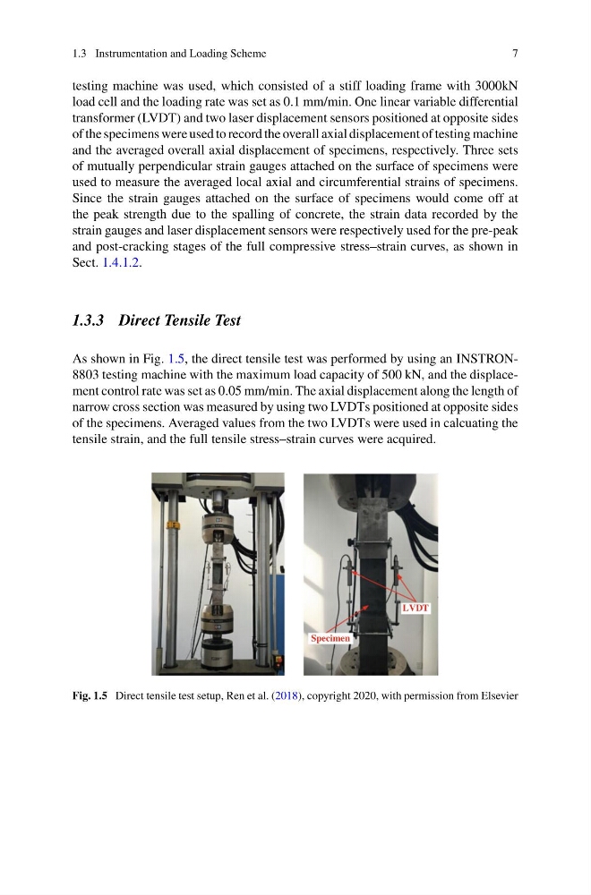
As shown in Fig. 1.5, the direct tensile test was performed by using an INSTRON8803 testing machine with the maximum load capacity of 500 kN, and the displacement control rate was set as 0.05 mm/min. The axial displacement along the length of
narrow cross section was measured by using two LVDTs positioned at opposite sides
of the specimens. Averaged values from the two LVDTs were used in calcuating the
tensile strain, and the full tensile stress–strain curves were acquired.
LVDT
Specimen
LVDT
Specimen
Fig. 1.5 Direct tensile test setup, Ren et al. (2018), copyright 2020, with permission from Elsevier
7
testing machine was used, which consisted of a stiff loading frame with 3000kN
load cell and the loading rate was set as 0.1 mm/min. One linear variable differential
transformer (LVDT) and two laser displacement sensors positioned at opposite sides
of the specimens were used to record the overall axial displacement of testing machine
and the averaged overall axial displacement of specimens, respectively. Three sets
of mutually perpendicular strain gauges attached on the surface of specimens were
used to measure the averaged local axial and circumferential strains of specimens.
Since the strain gauges attached on the surface of specimens would come off at
the peak strength due to the spalling of concrete, the strain data recorded by the
strain gauges and laser displacement sensors were respectively used for the pre-peak
and post-cracking stages of the full compressive stress–strain curves, as shown in
Sect. 1.4.1.2.
1.3.3 Direct Tensile Test
As shown in Fig. 1.5, the direct tensile test was performed by using an INSTRON8803 testing machine with the maximum load capacity of 500 kN, and the displacement control rate was set as 0.05 mm/min. The axial displacement along the length of
narrow cross section was measured by using two LVDTs positioned at opposite sides
of the specimens. Averaged values from the two LVDTs were used in calcuating the
tensile strain, and the full tensile stress–strain curves were acquired.
LVDT
Specimen
LVDT
Specimen
Fig. 1.5 Direct tensile test setup, Ren et al. (2018), copyright 2020, with permission from Elsevier