

252
8 Response of UHPCC-FST Subjected to Low-Velocity Impact
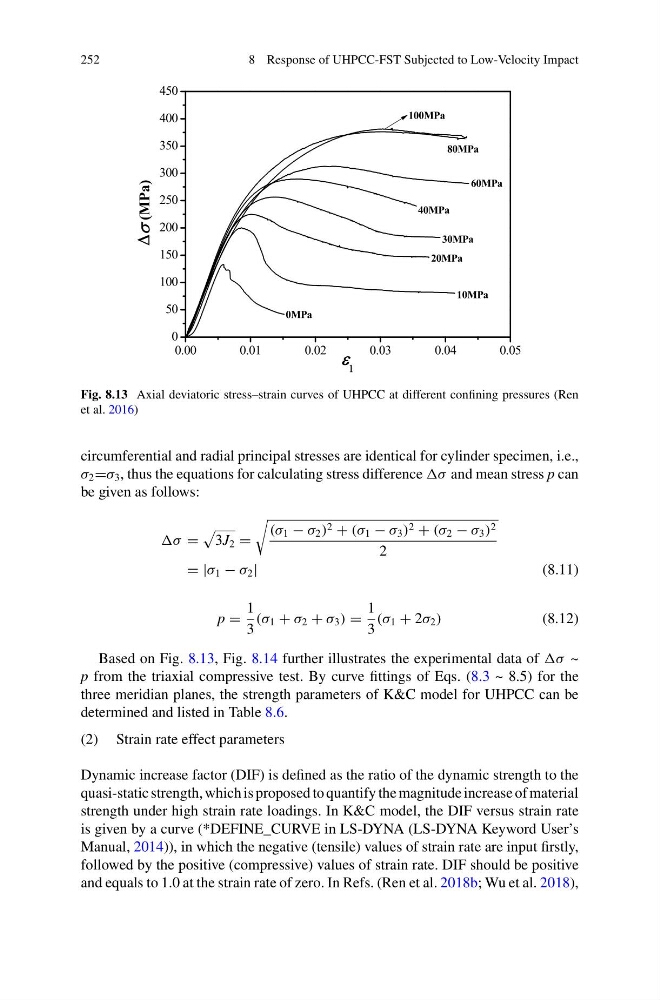
Fig. 8.13 Axial deviatoric stress–strain curves of UHPCC at different confining pressures (Ren
et al. 2016)
circumferential and radial principal stresses are identical for cylinder specimen, i.e.,
σ 2 =σ 3 , thus the equations for calculating stress difference σ and mean stress p can
be given as follows:
=
3J 2 =
(σ 1 − σ 2 ) 2 + (σ 1 − σ 3 ) 2 + (σ 2 − σ 3 ) 2
2
= |σ 1 − σ 2 |
(8.11)
p =
1
3
(σ 1 + σ 2 + σ 3 ) =
1
3
(σ 1 + 2σ 2 )
(8.12)
Based on Fig. 8.13, Fig. 8.14 further illustrates the experimental data of ~
p from the triaxial compressive test. By curve fittings of Eqs. (8.3 ~ 8.5) for the
three meridian planes, the strength parameters of K&C model for UHPCC can be
determined and listed in Table 8.6.
(2) Strain rate effect parameters
Dynamic increase factor (DIF) is defined as the ratio of the dynamic strength to the
quasi-static strength, which is proposed to quantify the magnitude increase of material
strength under high strain rate loadings. In K&C model, the DIF versus strain rate
is given by a curve (*DEFINE_CURVE in LS-DYNA (LS-DYNA Keyword User’s
Manual, 2014)), in which the negative (tensile) values of strain rate are input firstly,
followed by the positive (compressive) values of strain rate. DIF should be positive
and equals to 1.0 at the strain rate of zero. In Refs. (Ren et al. 2018b; Wu et al. 2018),
8 Response of UHPCC-FST Subjected to Low-Velocity Impact
Fig. 8.13 Axial deviatoric stress–strain curves of UHPCC at different confining pressures (Ren
et al. 2016)
circumferential and radial principal stresses are identical for cylinder specimen, i.e.,
σ 2 =σ 3 , thus the equations for calculating stress difference σ and mean stress p can
be given as follows:
=
3J 2 =
(σ 1 − σ 2 ) 2 + (σ 1 − σ 3 ) 2 + (σ 2 − σ 3 ) 2
2
= |σ 1 − σ 2 |
(8.11)
p =
1
3
(σ 1 + σ 2 + σ 3 ) =
1
3
(σ 1 + 2σ 2 )
(8.12)
Based on Fig. 8.13, Fig. 8.14 further illustrates the experimental data of ~
p from the triaxial compressive test. By curve fittings of Eqs. (8.3 ~ 8.5) for the
three meridian planes, the strength parameters of K&C model for UHPCC can be
determined and listed in Table 8.6.
(2) Strain rate effect parameters
Dynamic increase factor (DIF) is defined as the ratio of the dynamic strength to the
quasi-static strength, which is proposed to quantify the magnitude increase of material
strength under high strain rate loadings. In K&C model, the DIF versus strain rate
is given by a curve (*DEFINE_CURVE in LS-DYNA (LS-DYNA Keyword User’s
Manual, 2014)), in which the negative (tensile) values of strain rate are input firstly,
followed by the positive (compressive) values of strain rate. DIF should be positive
and equals to 1.0 at the strain rate of zero. In Refs. (Ren et al. 2018b; Wu et al. 2018),