

242
8 Response of UHPCC-FST Subjected to Low-Velocity Impact
2000
203
400
6
Cross-Section
Isometric view
UHPCC
Steel tube
20
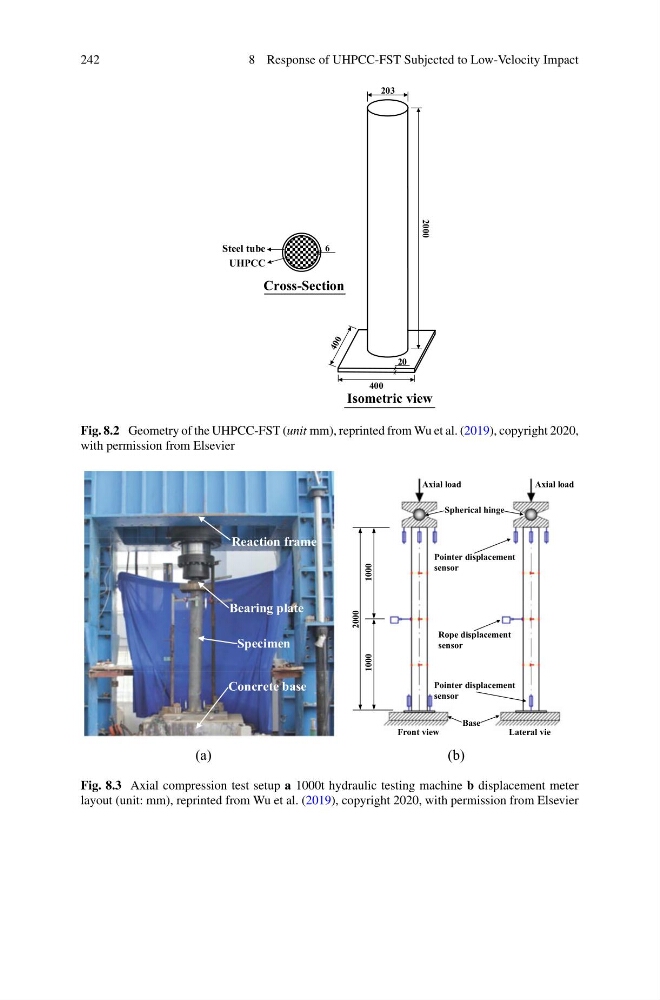
Fig. 8.2 Geometry of the UHPCC-FST (unit mm), reprinted from Wu et al. (2019), copyright 2020,
with permission from Elsevier
Fig. 8.3 Axial compression test setup a 1000t hydraulic testing machine b displacement meter
layout (unit: mm), reprinted from Wu et al. (2019), copyright 2020, with permission from Elsevier
8 Response of UHPCC-FST Subjected to Low-Velocity Impact
2000
203
400
6
Cross-Section
Isometric view
UHPCC
Steel tube
20
Fig. 8.2 Geometry of the UHPCC-FST (unit mm), reprinted from Wu et al. (2019), copyright 2020,
with permission from Elsevier
Fig. 8.3 Axial compression test setup a 1000t hydraulic testing machine b displacement meter
layout (unit: mm), reprinted from Wu et al. (2019), copyright 2020, with permission from Elsevier