

218
7 Impact Resistance of Armor Steel/Ceramic/UHPCC Layered …
150mm
150mm
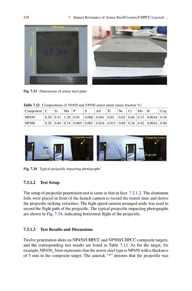
Fig. 7.33 Dimensions of armor steel plate
Table 7.12 Compositions of NP450 and NP500 armor steels (mass fraction %)
Component C
Si
Mn P
S
Alt
Ti
Ni
Cr
Mo B
Ceq
NP450
0.20 0.51 1.29 0.01 0.008 0.041 0.02 0.02 0.66 0.15 0.0018 0.58
NP500
0.28 0.64 0.74 0.005 0.001 0.034 0.015 0.69 0.24 0.42 0.0016 0.60
Projectile
Aluminum foil
Composite target
Projectile
Aluminum foil
Composite target
Fig. 7.34 Typical projectile impacting photographs
7.3.1.2 Test Setup
The setup of projectile penetration test is same as that in Sect. 7.2.1.2. The aluminum
foils were placed in front of the launch cannon to record the transit time and derive
the projectile striking velocities. The high-speed camera arranged aside was used to
record the flight path of the projectile. The typical projectile impacting photographs
are shown in Fig. 7.34, indicating horizontal flight of the projectile.
7.3.1.3 Test Results and Discussions
Twelve penetration shots on NP450/UHPCC and NP500/UHPCC composite targets,
and the corresponding test results are listed in Table 7.13. As for the target, for
example, NP450_5mm represents that the armor steel type is NP450 with a thickness
of 5 mm in the composite target. The asterisk “*” denotes that the projectile was
7 Impact Resistance of Armor Steel/Ceramic/UHPCC Layered …
150mm
150mm
Fig. 7.33 Dimensions of armor steel plate
Table 7.12 Compositions of NP450 and NP500 armor steels (mass fraction %)
Component C
Si
Mn P
S
Alt
Ti
Ni
Cr
Mo B
Ceq
NP450
0.20 0.51 1.29 0.01 0.008 0.041 0.02 0.02 0.66 0.15 0.0018 0.58
NP500
0.28 0.64 0.74 0.005 0.001 0.034 0.015 0.69 0.24 0.42 0.0016 0.60
Projectile
Aluminum foil
Composite target
Projectile
Aluminum foil
Composite target
Fig. 7.34 Typical projectile impacting photographs
7.3.1.2 Test Setup
The setup of projectile penetration test is same as that in Sect. 7.2.1.2. The aluminum
foils were placed in front of the launch cannon to record the transit time and derive
the projectile striking velocities. The high-speed camera arranged aside was used to
record the flight path of the projectile. The typical projectile impacting photographs
are shown in Fig. 7.34, indicating horizontal flight of the projectile.
7.3.1.3 Test Results and Discussions
Twelve penetration shots on NP450/UHPCC and NP500/UHPCC composite targets,
and the corresponding test results are listed in Table 7.13. As for the target, for
example, NP450_5mm represents that the armor steel type is NP450 with a thickness
of 5 mm in the composite target. The asterisk “*” denotes that the projectile was