

194
7 Impact Resistance of Armor Steel/Ceramic/UHPCC Layered …
Projectile
Tinfoil
Target
Target
Tinfoil
Projectile
Projectile
Target
Tinfoil
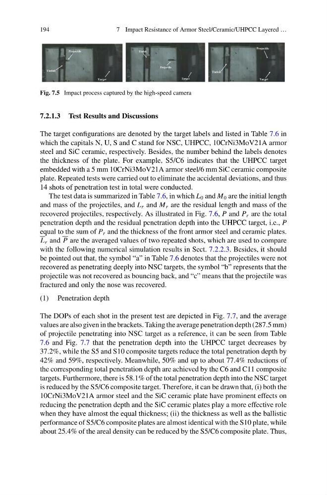
Fig. 7.5 Impact process captured by the high-speed camera
7.2.1.3 Test Results and Discussions
The target configurations are denoted by the target labels and listed in Table 7.6 in
which the capitals N, U, S and C stand for NSC, UHPCC, 10CrNi3MoV21A armor
steel and SiC ceramic, respectively. Besides, the number behind the labels denotes
the thickness of the plate. For example, S5/C6 indicates that the UHPCC target
embedded with a 5 mm 10CrNi3MoV21A armor steel/6 mm SiC ceramic composite
plate. Repeated tests were carried out to eliminate the accidental deviations, and thus
14 shots of penetration test in total were conducted.
The test data is summarized in Table 7.6, in which L 0 and M 0 are the initial length
and mass of the projectiles, and L r and M r are the residual length and mass of the
recovered projectiles, respectively. As illustrated in Fig. 7.6, P and P r are the total
penetration depth and the residual penetration depth into the UHPCC target, i.e., P
equal to the sum of P r and the thickness of the front armor steel and ceramic plates.
L r and P are the averaged values of two repeated shots, which are used to compare
with the following numerical simulation results in Sect. 7.2.2.3. Besides, it should
be pointed out that, the symbol “a” in Table 7.6 denotes that the projectiles were not
recovered as penetrating deeply into NSC targets, the symbol “b” represents that the
projectile was not recovered as bouncing back, and “c” means that the projectile was
fractured and only the nose was recovered.
(1) Penetration depth
The DOPs of each shot in the present test are depicted in Fig. 7.7, and the average
values are also given in the brackets. Taking the average penetration depth (287.5 mm)
of projectile penetrating into NSC target as a reference, it can be seen from Table
7.6 and Fig. 7.7 that the penetration depth into the UHPCC target decreases by
37.2%, while the S5 and S10 composite targets reduce the total penetration depth by
42% and 59%, respectively. Meanwhile, 50% and up to about 77.4% reductions of
the corresponding total penetration depth are achieved by the C6 and C11 composite
targets. Furthermore, there is 58.1% of the total penetration depth into the NSC target
is reduced by the S5/C6 composite target. Therefore, it can be drawn that, (i) both the
10CrNi3MoV21A armor steel and the SiC ceramic plate have prominent effects on
reducing the penetration depth and the SiC ceramic plates play a more effective role
when they have almost the equal thickness; (ii) the thickness as well as the ballistic
performance of S5/C6 composite plates are almost identical with the S10 plate, while
about 25.4% of the areal density can be reduced by the S5/C6 composite plate. Thus,
7 Impact Resistance of Armor Steel/Ceramic/UHPCC Layered …
Projectile
Tinfoil
Target
Target
Tinfoil
Projectile
Projectile
Target
Tinfoil
Fig. 7.5 Impact process captured by the high-speed camera
7.2.1.3 Test Results and Discussions
The target configurations are denoted by the target labels and listed in Table 7.6 in
which the capitals N, U, S and C stand for NSC, UHPCC, 10CrNi3MoV21A armor
steel and SiC ceramic, respectively. Besides, the number behind the labels denotes
the thickness of the plate. For example, S5/C6 indicates that the UHPCC target
embedded with a 5 mm 10CrNi3MoV21A armor steel/6 mm SiC ceramic composite
plate. Repeated tests were carried out to eliminate the accidental deviations, and thus
14 shots of penetration test in total were conducted.
The test data is summarized in Table 7.6, in which L 0 and M 0 are the initial length
and mass of the projectiles, and L r and M r are the residual length and mass of the
recovered projectiles, respectively. As illustrated in Fig. 7.6, P and P r are the total
penetration depth and the residual penetration depth into the UHPCC target, i.e., P
equal to the sum of P r and the thickness of the front armor steel and ceramic plates.
L r and P are the averaged values of two repeated shots, which are used to compare
with the following numerical simulation results in Sect. 7.2.2.3. Besides, it should
be pointed out that, the symbol “a” in Table 7.6 denotes that the projectiles were not
recovered as penetrating deeply into NSC targets, the symbol “b” represents that the
projectile was not recovered as bouncing back, and “c” means that the projectile was
fractured and only the nose was recovered.
(1) Penetration depth
The DOPs of each shot in the present test are depicted in Fig. 7.7, and the average
values are also given in the brackets. Taking the average penetration depth (287.5 mm)
of projectile penetrating into NSC target as a reference, it can be seen from Table
7.6 and Fig. 7.7 that the penetration depth into the UHPCC target decreases by
37.2%, while the S5 and S10 composite targets reduce the total penetration depth by
42% and 59%, respectively. Meanwhile, 50% and up to about 77.4% reductions of
the corresponding total penetration depth are achieved by the C6 and C11 composite
targets. Furthermore, there is 58.1% of the total penetration depth into the NSC target
is reduced by the S5/C6 composite target. Therefore, it can be drawn that, (i) both the
10CrNi3MoV21A armor steel and the SiC ceramic plate have prominent effects on
reducing the penetration depth and the SiC ceramic plates play a more effective role
when they have almost the equal thickness; (ii) the thickness as well as the ballistic
performance of S5/C6 composite plates are almost identical with the S10 plate, while
about 25.4% of the areal density can be reduced by the S5/C6 composite plate. Thus,