

174
6 Impact Resistance of Basalt Aggregated UHP-SFRC/Fabric …
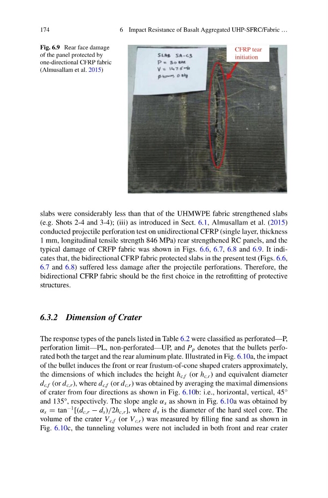
Fig. 6.9 Rear face damage
of the panel protected by
one-directional CFRP fabric
(Almusallam et al. 2015)
CFRP tear
initiation
slabs were considerably less than that of the UHMWPE fabric strengthened slabs
(e.g. Shots 2-4 and 3-4); (iii) as introduced in Sect. 6.1, Almusallam et al. (2015)
conducted projectile perforation test on unidirectional CFRP (single layer, thickness
1 mm, longitudinal tensile strength 846 MPa) rear strengthened RC panels, and the
typical damage of CRFP fabric was shown in Figs. 6.6, 6.7, 6.8 and 6.9. It indicates that, the bidirectional CFRP fabric protected slabs in the present test (Figs. 6.6,
6.7 and 6.8) suffered less damage after the projectile perforations. Therefore, the
bidirectional CFRP fabric should be the first choice in the retrofitting of protective
structures.
6.3.2 Dimension of Crater
The response types of the panels listed in Table 6.2 were classified as perforated—P,
perforation limit—PL, non-perforated—UP, and P p denotes that the bullets perforated both the target and the rear aluminum plate. Illustrated in Fig. 6.10a, the impact
of the bullet induces the front or rear frustum-of-cone shaped craters approximately,
the dimensions of which includes the height h c,f (or h c,r ) and equivalent diameter
d c,f (or d c,r ), where d c,f (or d c,r ) was obtained by averaging the maximal dimensions
of crater from four directions as shown in Fig. 6.10b: i.e., horizontal, vertical, 45°
and 135°, respectively. The slope angle α s as shown in Fig. 6.10a was obtained by
α s = tan
−1
[(d c,r − d s )/2h c,r ], where d s is the diameter of the hard steel core. The
volume of the crater V c,f (or V c,r ) was measured by filling fine sand as shown in
Fig. 6.10c, the tunneling volumes were not included in both front and rear crater
6 Impact Resistance of Basalt Aggregated UHP-SFRC/Fabric …
Fig. 6.9 Rear face damage
of the panel protected by
one-directional CFRP fabric
(Almusallam et al. 2015)
CFRP tear
initiation
slabs were considerably less than that of the UHMWPE fabric strengthened slabs
(e.g. Shots 2-4 and 3-4); (iii) as introduced in Sect. 6.1, Almusallam et al. (2015)
conducted projectile perforation test on unidirectional CFRP (single layer, thickness
1 mm, longitudinal tensile strength 846 MPa) rear strengthened RC panels, and the
typical damage of CRFP fabric was shown in Figs. 6.6, 6.7, 6.8 and 6.9. It indicates that, the bidirectional CFRP fabric protected slabs in the present test (Figs. 6.6,
6.7 and 6.8) suffered less damage after the projectile perforations. Therefore, the
bidirectional CFRP fabric should be the first choice in the retrofitting of protective
structures.
6.3.2 Dimension of Crater
The response types of the panels listed in Table 6.2 were classified as perforated—P,
perforation limit—PL, non-perforated—UP, and P p denotes that the bullets perforated both the target and the rear aluminum plate. Illustrated in Fig. 6.10a, the impact
of the bullet induces the front or rear frustum-of-cone shaped craters approximately,
the dimensions of which includes the height h c,f (or h c,r ) and equivalent diameter
d c,f (or d c,r ), where d c,f (or d c,r ) was obtained by averaging the maximal dimensions
of crater from four directions as shown in Fig. 6.10b: i.e., horizontal, vertical, 45°
and 135°, respectively. The slope angle α s as shown in Fig. 6.10a was obtained by
α s = tan
−1
[(d c,r − d s )/2h c,r ], where d s is the diameter of the hard steel core. The
volume of the crater V c,f (or V c,r ) was measured by filling fine sand as shown in
Fig. 6.10c, the tunneling volumes were not included in both front and rear crater