

6.2 Bullet Perforation Test
169
(a)
(b)
0
2
4
6
8
1 0
1 2
1 4
0
20
40
60
80
100
120
Stress (MPa)
Displacement (mm)
0.00
0.05
0.10
0.15
0.20
0.25
0.30
0
1
2
3
4
5
6
7
Stress (MPa)
Strain
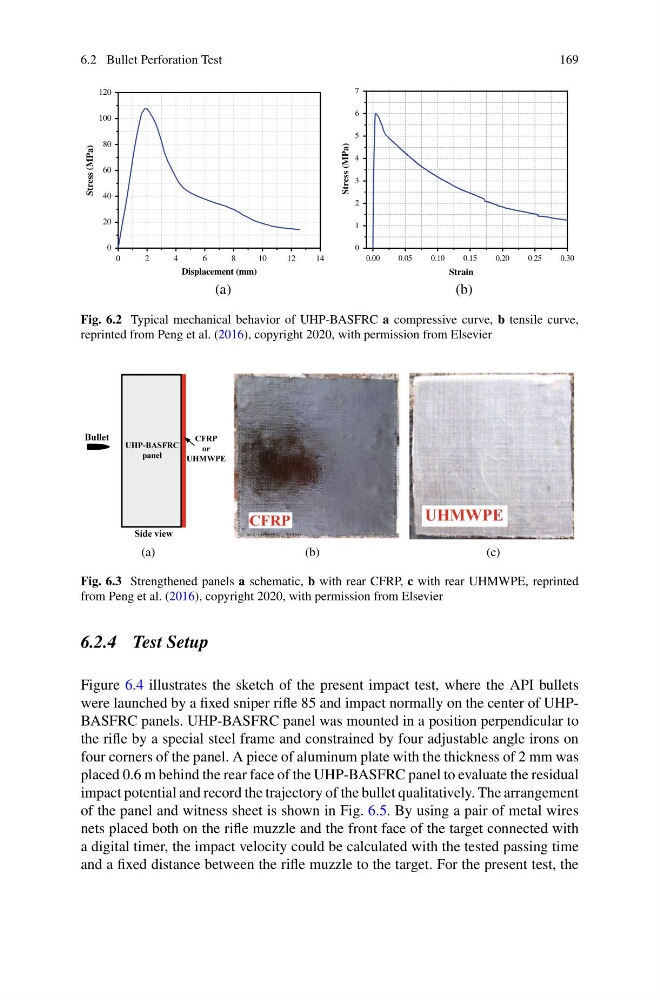
Fig. 6.2 Typical mechanical behavior of UHP-BASFRC a compressive curve, b tensile curve,
reprinted from Peng et al. (2016), copyright 2020, with permission from Elsevier
(a)
(b)
(c)
CFRP
UHMWPE
Fig. 6.3 Strengthened panels a schematic, b with rear CFRP, c with rear UHMWPE, reprinted
from Peng et al. (2016), copyright 2020, with permission from Elsevier
6.2.4 Test Setup
Figure 6.4 illustrates the sketch of the present impact test, where the API bullets
were launched by a fixed sniper rifle 85 and impact normally on the center of UHPBASFRC panels. UHP-BASFRC panel was mounted in a position perpendicular to
the rifle by a special steel frame and constrained by four adjustable angle irons on
four corners of the panel. A piece of aluminum plate with the thickness of 2 mm was
placed 0.6 m behind the rear face of the UHP-BASFRC panel to evaluate the residual
impact potential and record the trajectory of the bullet qualitatively. The arrangement
of the panel and witness sheet is shown in Fig. 6.5. By using a pair of metal wires
nets placed both on the rifle muzzle and the front face of the target connected with
a digital timer, the impact velocity could be calculated with the tested passing time
and a fixed distance between the rifle muzzle to the target. For the present test, the
169
(a)
(b)
0
2
4
6
8
1 0
1 2
1 4
0
20
40
60
80
100
120
Stress (MPa)
Displacement (mm)
0.00
0.05
0.10
0.15
0.20
0.25
0.30
0
1
2
3
4
5
6
7
Stress (MPa)
Strain
Fig. 6.2 Typical mechanical behavior of UHP-BASFRC a compressive curve, b tensile curve,
reprinted from Peng et al. (2016), copyright 2020, with permission from Elsevier
(a)
(b)
(c)
CFRP
UHMWPE
Fig. 6.3 Strengthened panels a schematic, b with rear CFRP, c with rear UHMWPE, reprinted
from Peng et al. (2016), copyright 2020, with permission from Elsevier
6.2.4 Test Setup
Figure 6.4 illustrates the sketch of the present impact test, where the API bullets
were launched by a fixed sniper rifle 85 and impact normally on the center of UHPBASFRC panels. UHP-BASFRC panel was mounted in a position perpendicular to
the rifle by a special steel frame and constrained by four adjustable angle irons on
four corners of the panel. A piece of aluminum plate with the thickness of 2 mm was
placed 0.6 m behind the rear face of the UHP-BASFRC panel to evaluate the residual
impact potential and record the trajectory of the bullet qualitatively. The arrangement
of the panel and witness sheet is shown in Fig. 6.5. By using a pair of metal wires
nets placed both on the rifle muzzle and the front face of the target connected with
a digital timer, the impact velocity could be calculated with the tested passing time
and a fixed distance between the rifle muzzle to the target. For the present test, the