

122
5 Projectile Penetrations into Coarse Aggregated UHPCC Targets
Table 5.3 Compositions of UHP-CASFRC and HSC targets (kg/m 3 )
Cement Silica
fume
Fly
ash
Slag
Sand
V c
w/cm
ratio
HRWR V f
UHP-CASFRC 377–480 63–80 63–80 126–160 629–800 800–1700 0.26 1.5–16 160
HSC
266
–
38
76
720
1090
0.58 1.5
0
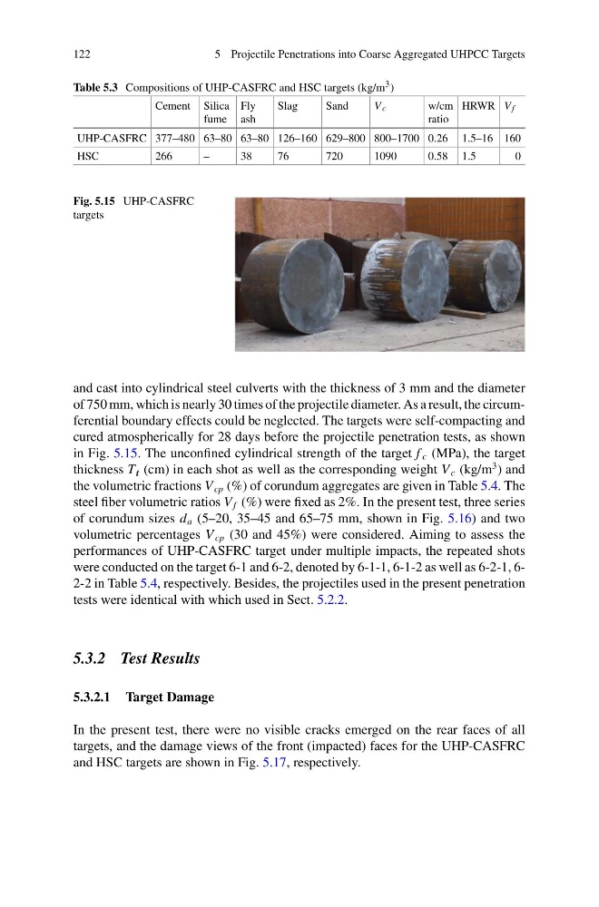
Fig. 5.15 UHP-CASFRC
targets
and cast into cylindrical steel culverts with the thickness of 3 mm and the diameter
of 750 mm, which is nearly 30 times of the projectile diameter. As a result, the circumferential boundary effects could be neglected. The targets were self-compacting and
cured atmospherically for 28 days before the projectile penetration tests, as shown
in Fig. 5.15. The unconfined cylindrical strength of the target f c (MPa), the target
thickness T t (cm) in each shot as well as the corresponding weight V c (kg/m
3 ) and
the volumetric fractions V cp (%) of corundum aggregates are given in Table 5.4. The
steel fiber volumetric ratios V f (%) were fixed as 2%. In the present test, three series
of corundum sizes d a (5–20, 35–45 and 65–75 mm, shown in Fig. 5.16) and two
volumetric percentages V cp (30 and 45%) were considered. Aiming to assess the
performances of UHP-CASFRC target under multiple impacts, the repeated shots
were conducted on the target 6-1 and 6-2, denoted by 6-1-1, 6-1-2 as well as 6-2-1, 62-2 in Table 5.4, respectively. Besides, the projectiles used in the present penetration
tests were identical with which used in Sect. 5.2.2.
5.3.2 Test Results
5.3.2.1 Target Damage
In the present test, there were no visible cracks emerged on the rear faces of all
targets, and the damage views of the front (impacted) faces for the UHP-CASFRC
and HSC targets are shown in Fig. 5.17, respectively.
5 Projectile Penetrations into Coarse Aggregated UHPCC Targets
Table 5.3 Compositions of UHP-CASFRC and HSC targets (kg/m 3 )
Cement Silica
fume
Fly
ash
Slag
Sand
V c
w/cm
ratio
HRWR V f
UHP-CASFRC 377–480 63–80 63–80 126–160 629–800 800–1700 0.26 1.5–16 160
HSC
266
–
38
76
720
1090
0.58 1.5
0
Fig. 5.15 UHP-CASFRC
targets
and cast into cylindrical steel culverts with the thickness of 3 mm and the diameter
of 750 mm, which is nearly 30 times of the projectile diameter. As a result, the circumferential boundary effects could be neglected. The targets were self-compacting and
cured atmospherically for 28 days before the projectile penetration tests, as shown
in Fig. 5.15. The unconfined cylindrical strength of the target f c (MPa), the target
thickness T t (cm) in each shot as well as the corresponding weight V c (kg/m
3 ) and
the volumetric fractions V cp (%) of corundum aggregates are given in Table 5.4. The
steel fiber volumetric ratios V f (%) were fixed as 2%. In the present test, three series
of corundum sizes d a (5–20, 35–45 and 65–75 mm, shown in Fig. 5.16) and two
volumetric percentages V cp (30 and 45%) were considered. Aiming to assess the
performances of UHP-CASFRC target under multiple impacts, the repeated shots
were conducted on the target 6-1 and 6-2, denoted by 6-1-1, 6-1-2 as well as 6-2-1, 62-2 in Table 5.4, respectively. Besides, the projectiles used in the present penetration
tests were identical with which used in Sect. 5.2.2.
5.3.2 Test Results
5.3.2.1 Target Damage
In the present test, there were no visible cracks emerged on the rear faces of all
targets, and the damage views of the front (impacted) faces for the UHP-CASFRC
and HSC targets are shown in Fig. 5.17, respectively.